
Polymer organic light-emitting device

a light-emitting device and organic technology, applied in the direction of organic semiconductor devices, auxillary members of forms/shuttering/falseworks, discharge tubes luminescnet screens, etc., can solve the problems of reducing the number of holes that can be transported into the recombination zone, generating an insoluble layer, and reducing the recombination zone. , to achieve the effect of improving the properties of electron density, brightness, and color purity

Inactive Publication Date: 2007-07-05
SAMSUNG MOBILE DISPLAY CO LTD
View PDF0 Cites 33 Cited by
  • Summary
  • Abstract
  • Description
  • Claims
  • Application Information

AI Technical Summary

Benefits of technology

[0012]The present invention provides a polymer organic light-emitting device (OLED) which has improved properties of electron density, luminance and color purity.
[0022]The polymer OLED of the present invention, in which a emission layer includes a hole transport polymeric material, provides improved properties of electron density, brightness, and color purity, and these properties are not deteriorated in spite of the generation of an insoluble layer within the emission layer.

Problems solved by technology

However, OLEDs that are made of conventional polymers have relatively higher electron mobility than hole mobility during operation, which causes holes and electrons to meet each other near an anode side in an emission layer.
On the other hand, when the OLEDs that are made of conventional polymers are operated, cross-linking between polymer chains, which is caused by electro-chemical reactions, is generated at the region near the anode, which results in the generation of an insoluble layer.
Such an insoluble layer lowers the hole mobility, which results in a decrease in the number of holes that can be transported into the recombination zone.
As a result, the recombination zone becomes smaller, and the efficiency and the lifetime of the OLEDs decrease.

Method used


Image

  • Polymer organic light-emitting device
  • Polymer organic light-emitting device
  • Polymer organic light-emitting device

Examples


example 1

[0072]A polymer OLED having the following structure was manufactured using PVK as a dopant of an EML: ITO / (PEDOT:PSS) (50 nm) / Formula 2+PVK (70 nm) / BaF2 (4 nm) / Ca (2 nm) / Al (150 nm).

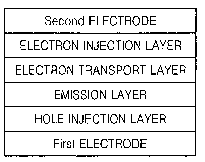
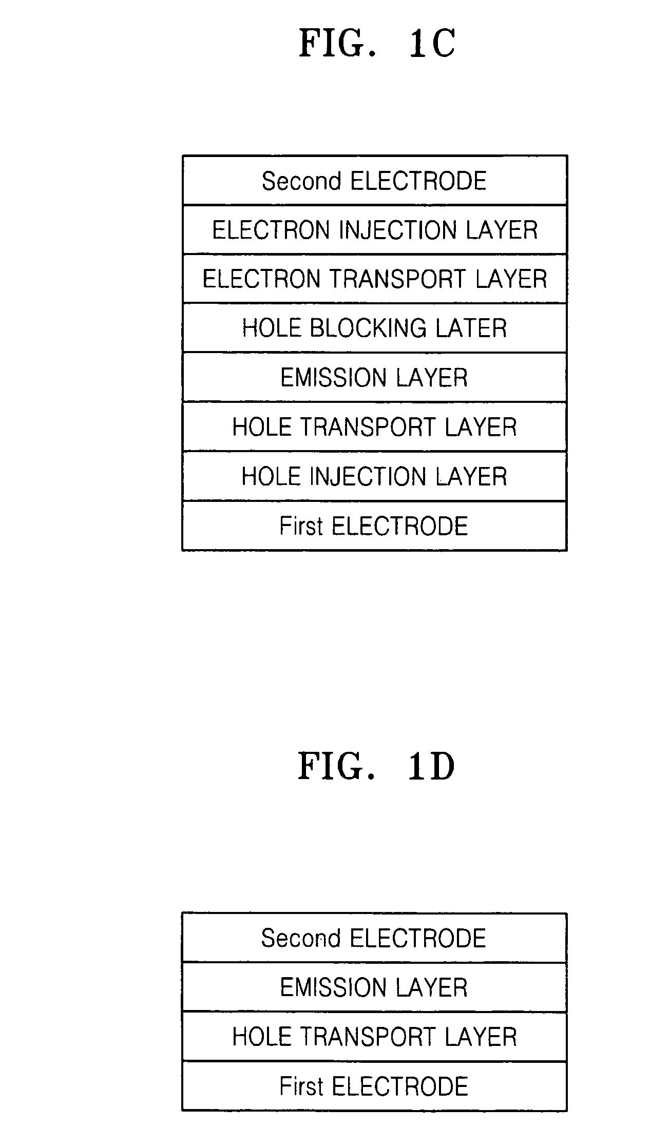
[0073]As an anode, a 15Ω / cm2 (1500 Å) ITO glass substrate from Corning Inc. was cut into pieces of 50 mm×0.7 mm, cleaned by ultrasonic agitation in a mixture of pure water and isopropyl alcohol for 5 minutes, and then was cleaned with UV radiation and O3 for 10 minutes before use. PEDOT:PSS was coated on the glass substrate and baked at 120° C. for 10 minutes to form a HTL having a thickness of 500 Å. Subsequently, Formula 2+PVK (prepared in a ratio of 1:1 by weight of Formula 2 to PVK) was spin-coated, and was heat-treated at 200° C. for 1 hour to form an EML having a thickness of 700 Å. Then, (BaF24 nm / Ca2 nm / Al150 nm cathode) was vacuum-deposited on the EML to manufacture the polymer OLED shown in FIG. 1D, which was designated sample A.

example 2

[0074]A polymer OLED was manufactured in the same method as described in Example 1 except that Formula 3+PVK, instead of Formula 2+PVK, was used to form an EML.

example 3

[0075]A polymer OLED was manufactured in the same method as described in Example 1 except that the EML included 0.1 weight % of PVK, which is a hole transport material, with respect to the total weight of the EML.


PUM

PropertyMeasurementUnit
Percent by massaaaaaaaaaa
Thicknessaaaaaaaaaa

Abstract

A polymer organic light-emitting device (OLED) is provided to improve efficiency and lifetime of the polymer OLED by preventing the recombination zone from shrinking. The OLED includes a first electrode, a second electrode, and an emission layer disposed between the first electrode and the second electrode. The emission layer includes an emission material and a hole transport material. The emission layer can be built in a single layer or in multi-layers. In the multi-layer structure, one layer includes an emission material and a hole transport material, while the other layer includes an emission material. The polymer OLED presented in this invention exhibits superior properties regarding electron density, brightness, and color purity.

Description

CLAIM OF PRIORITY[0001]This application claims the benefit of Korean Patent Application No. 10-2006-0001390, filed on Jan. 5, 2006, in the Korean Intellectual Property Office, the disclosure of which is incorporated herein in its entirety by reference.BACKGROUND OF THE INVENTION[0002]1. Field of the Invention[0003]The present invention relates to a polymer organic light-emitting device (polymer OLED) including a hole transport material in an emission layer, and more particularly, to a polymer OLED including a hole transport material having an excellent hole transport capability in an emission layer and exhibiting improved properties such as electron density, brightness and color purity.[0004]2. Description of the Related Art[0005]A light-emitting device is a self light-emitting type device which has numerous advantages including wide viewing angle, superior contrast, and fast response time. A light-emitting device may be classified as an inorganic light-emitting device using inorgan...

Claims


Application Information

Patent Timeline
IPC IPC(8): H01L51/00
CPCC09K11/06H05B33/22C09K2211/1433C09K2211/1458C09K2211/1475H01L51/0035H01L51/0037H01L51/0039H01L51/0042H01L51/0043H01L51/5012H01L51/5016H01L51/5036H01L2251/558H05B33/14C09K2211/1425H10K85/146H10K85/115H10K85/111H10K85/1135H10K85/151H10K50/125H10K50/11H10K2101/10H10K2102/351E04G17/047
Inventor KIM, MU-GYEOMSON, JHUN-MOPARK, SANG-HOONPARK, JOON-YONGLEE, TAE-WOOKIM, SANG-YEOL
Owner SAMSUNG MOBILE DISPLAY CO LTD
Features
  • Generate Ideas
  • Intellectual Property
  • Life Sciences
  • Materials
  • Tech Scout
  • Unparalleled Data Quality
  • Higher Quality Content
  • 60% Fewer Hallucinations
Learn More