Display unit

a display unit and display technology, applied in the field of display units, can solve the problems of short circuit and difficult to avoid corrosion, and achieve the effects of preventing corrosion of metal wiring

Active Publication Date: 2007-07-05
JOLED INC
View PDF2 Cites 22 Cited by
  • Summary
  • Abstract
  • Description
  • Claims
  • Application Information

AI Technical Summary

Benefits of technology

[0010] In view of the foregoing, in the invention, it is desirable to provide a display unit capable of preventing the corrosion of the metal wiring and improving the reliability.
[0012] In the first display unit, the coating layer in the bonding region has the separated region between the plurality of metal wirings. Therefore, moisture and impurity ions are prevented from entering between the adjacent metal wirings through the coating layer.
[0015] According to the first display unit of the embodiment of the invention, at least one separated region is provided between the plurality of metal wirings in the coating layer in the bonding region. Therefore, moisture and impurity ions can be prevented from entering between the adjacent metal wirings through the coating layer. In the result, corrosion of the metal wiring is prevented, and the reliability of the display unit can be largely improved.
[0016] According to the second display unit of the embodiment of the invention, the plurality of metal wirings are coated with the coating layer on the terminal region side rather than the boundary between the terminal region and the bonding region. Therefore, moisture and impurity ions can be prevented from entering from the boundary into the bonding region through the coating layer. In the result, corrosion of the metal wiring is prevented, and the reliability of the display unit can be largely improved.

Problems solved by technology

In the result, corrosion is generated in the metal wiring 251, leading to breaking and short circuit.
Therefore, it has been difficult to avoid the corrosion even when the electric potential difference between the adjacent wirings is very small.

Method used


Image

  • Display unit
  • Display unit
  • Display unit

Examples


first embodiment

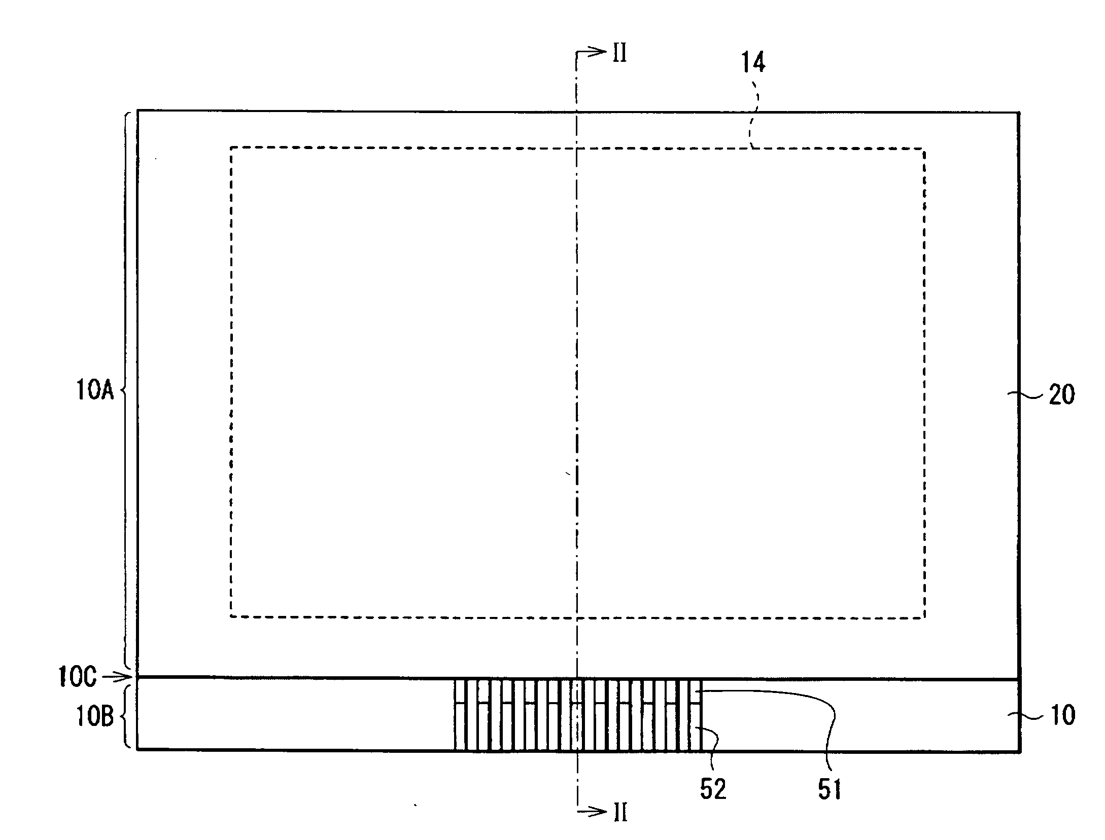
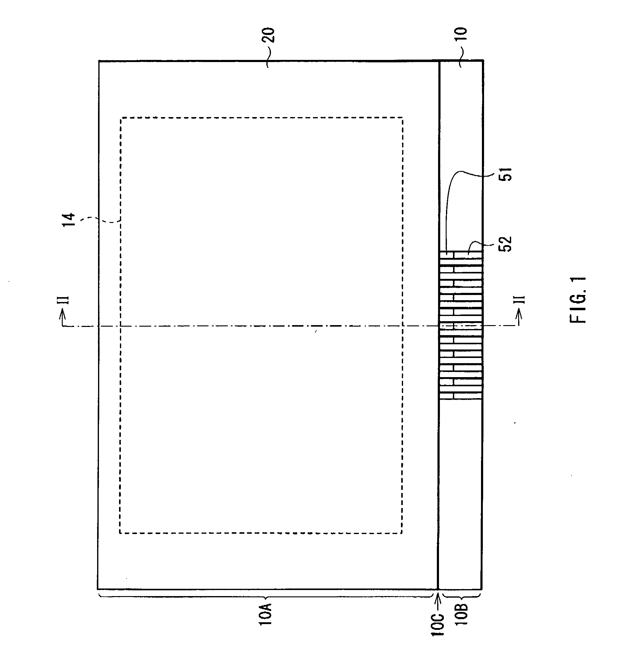
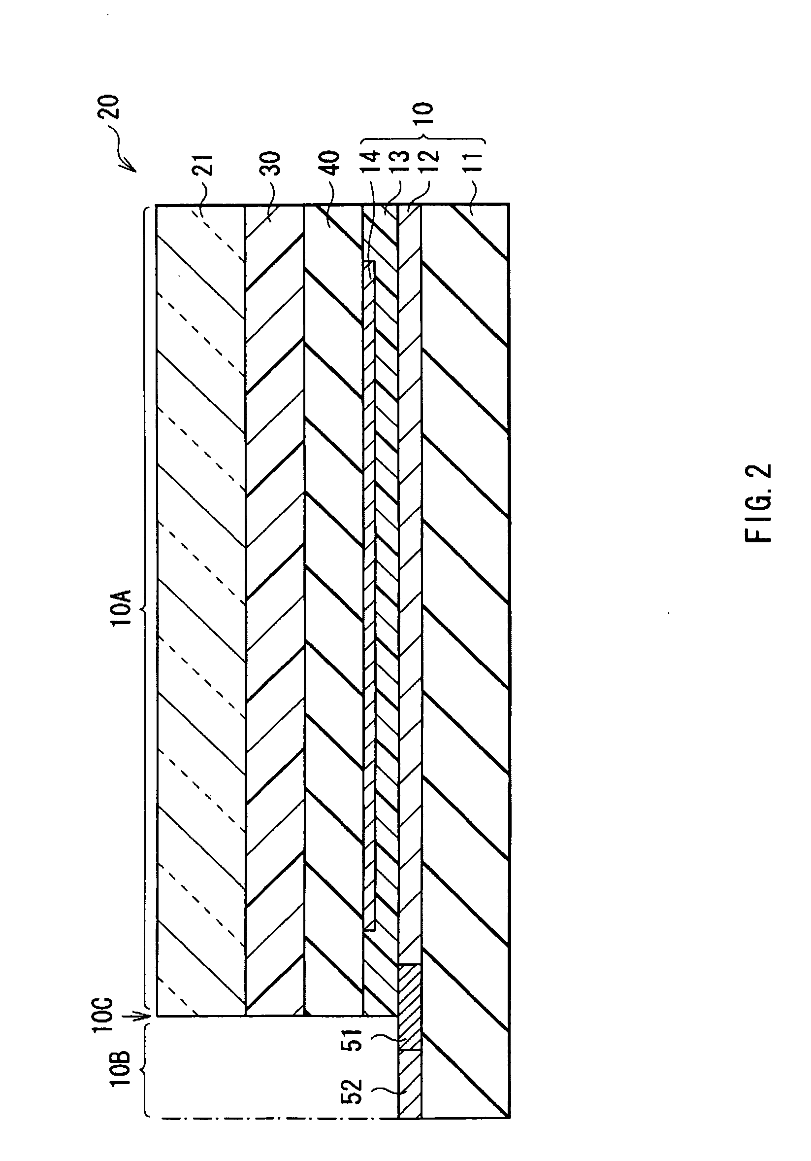
[0040]FIG. 1 shows a schematic structure of a display unit according to a first embodiment of the invention. FIG. 2 shows a cross sectional structure taken along line II-II of the display unit shown in FIG. 1. The display unit is used as an active-type / passive-type ultrathin organic light emitting display unit driven by a TFT (Thin Film Transistor), for example. The display unit has a structure in which a driving panel 10 and a sealing panel 20 are oppositely arranged and bonded with an adhesive layer 30 in between.

[0041] In the driving panel 10, a circuit section 12, a coating layer 13, and a display portion 14 composed of a plurality of organic light emitting devices described later are sequentially formed on a driving substrate 11 made of an inorganic insulating material such as glass. To seal the display portion 14 from the air, an inorganic insulating film 40 made of silicon nitride (SiNx), silicon dioxide (SiO2) or the like is provided between the display portion 14 side of t...

second modification

[0072]FIG. 11 shows a planar structure in the vicinity of the boundary 10C of a display unit according to the second modification of the invention. In the display unit, the coating layer 13 is provided on the whole area of the bonding region 10A and the terminal region 10B. In the coating layer 13, an aperture 13B is provided according to the terminal 52. In this modification, effects similar to those of the foregoing first modification can be obtained.

third modification

[0073]FIG. 12 shows a planar structure in the vicinity of the boundary 10C of a display unit according to the third modification of the invention. In the display unit, part of the coating layer 13 is removed to become a lateral separated region 13C extending in the array direction of the metal wiring 51. The lateral separated region 13C separates the section where the display portion 14 is formed on the coating layer 13 from the section where the coating layer 13 coats the metal wiring 51 in the vicinity of the boundary 10C. Thereby, in this modification, moisture and impurity ions can be surely prevented from entering between the metal wirings 51 in the vicinity of the boundary 10C through the coating layer 13.

[0074] The coating layer 13 may be provided with the aperture 13B according to the terminal 52 as shown in FIG. 12. Otherwise, as shown in FIG. 13, it is possible that the coating layer 13 coats only the metal wiring 51 and does not reach the terminal 52.


PUM

PropertyMeasurementUnit
thickaaaaaaaaaa
thickaaaaaaaaaa
widthaaaaaaaaaa

Abstract

A display unit capable of preventing corrosion of a metal wiring and improving the reliability is provided. The display unit includes a driving panel having a bonding region and a terminal region on a driving substrate, and a sealing panel being bonded on the bonding region of the driving panel with an adhesive layer in between. The bonding region includes a circuit section, a coating layer covering a circuit section, and a display portion composed of a plurality of display devices. A plurality of metal wirings are electrically connected to the circuit section in the bonding region and are extended to the terminal region. The coating layer has at least one separated region between the plurality of metal wirings.

Description

CROSS REFERENCES TO RELATED APPLICATIONS [0001] The present invention contains subject matter related to Japanese Patent Application JP 2005-354527 filed in the Japanese Patent Office on Dec. 8, 2005, the entire contents of which being incorporated herein by reference. BACKGROUND OF THE INVENTION [0002] 1. Field of the Invention [0003] The present invention relates to a display unit using display devices such as organic light emitting devices, and particularly to a display unit of a so-called completely solid sealing structure in which a driving panel provided with the display devices and a sealing panel are bonded with an adhesive layer in between. [0004] 2. Description of the Related Art [0005] In these years, as a display unit displacing a liquid crystal display, an organic light emitting display unit using organic light emitting devices has been noted. FIG. 19 and FIG. 20 show an example of the structure of the organic light emitting display unit. In the display unit, a driving ...

Claims


Application Information

Patent Timeline
Patent Type & Authority Applications(United States)
IPC IPC(8): G02F1/1345
CPCG02F1/1345G02F1/13458H01L51/5237H01L27/3276H01L27/3288H01L27/3258H10K59/124H10K59/179H10K59/131H10K50/841H10K50/844H05B33/04
Inventor SAKAGUCHI, MASAYUKIKANAYA, YASUHIROYAMAGUCHI, TOSHIAKIKUBOTA, SHINJITAKAGI, KAZUNARIYUMOTO, AKIRA
Owner JOLED INC
Why Eureka
Try Eureka