Centering pin

a technology of centering pins and pins, which is applied in the direction of threaded fasteners, screwdrivers, manufacturing tools, etc., can solve the problems of disadvantageous machining steps, two aforesaid pins entail not insubstantial production complexity, etc., and achieves a high degree of functional assurance, prevents extremely disadvantageous breakage, and relatively easy to break o

Inactive Publication Date: 2007-07-05
FRIATEC AG DE
View PDF13 Cites 5 Cited by
  • Summary
  • Abstract
  • Description
  • Claims
  • Application Information

AI Technical Summary

Benefits of technology

[0006] In contrast to receiving elements with tips made of ceramics, which can break off relatively easily, particularly when they have small diameters, using the metal tip prevents the extremely disadvantageous breakage with a high degree of functional assuredness. Thus components encountered in connection with the invention, in particular metal sheets, can be readily joined to one another using the suggested receiving elements, in particular in welding tools and / or pressure welding tools, even with threaded female elements that are quite small, in particular with M4, M5, M6, or M8 female threads, avoiding failure times and idle times for the welding tools or automatic welding systems and attaining long useful life periods. The bolt is advantageously produced, for example, by dry pressing, extrusion, or in an injection molding process and / or by mechanical processing. The bolt is advantageously embodied as a part, either as tube or bar, and is provided and / or fitted with the metal tip at the forward free end.
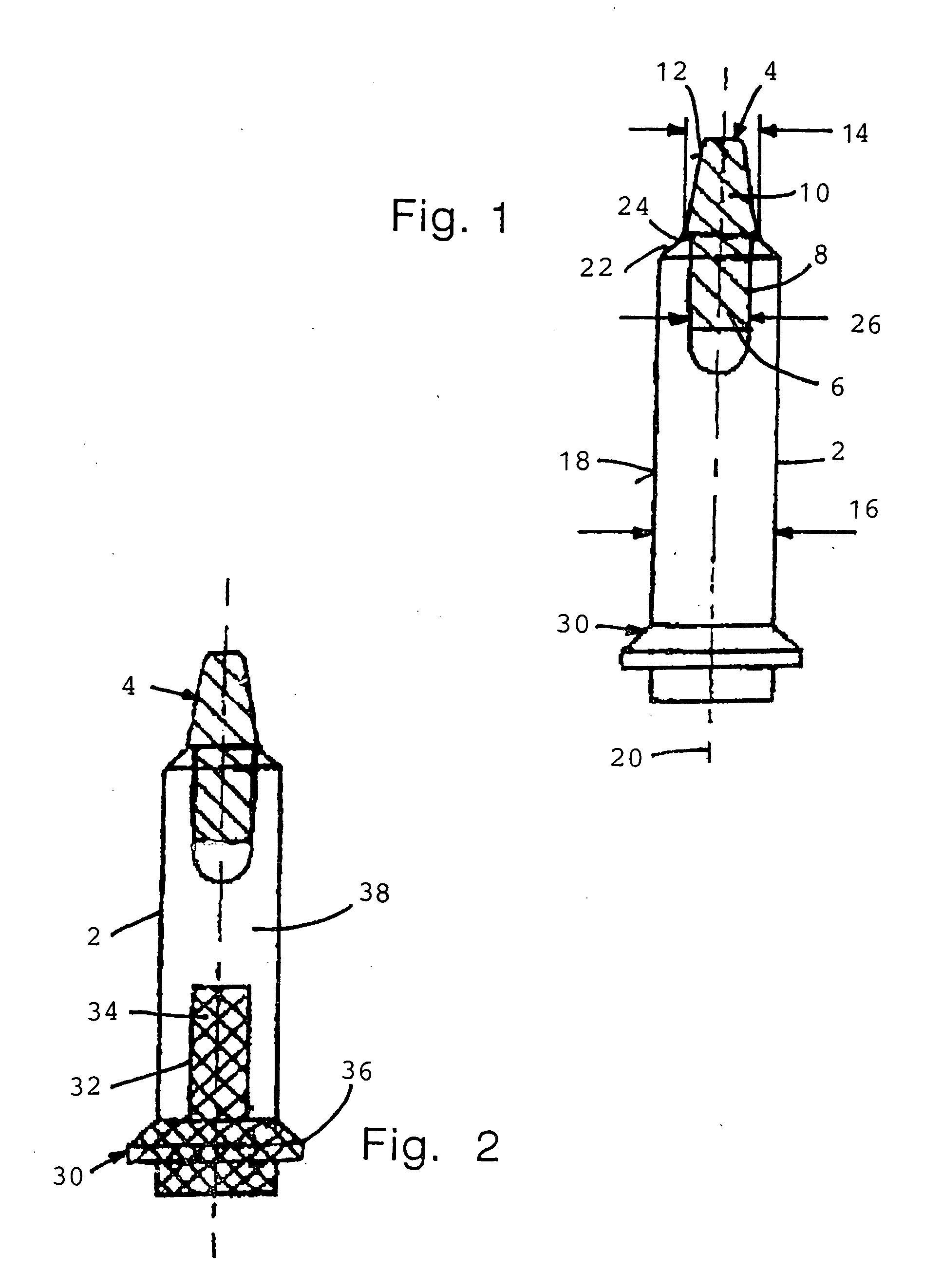
[0007] Moreover, in particular for optimizing the insulation, a fastening body made of an insulating material, advantageously, for example, plastic, can be provided at the other end of the bolt from the tip, an adhesive joint, shrink fit, press fit, or clamp connection preferably being provided. By using high-performance ceramics for the bolt in conjunction with the tip made of metal, advantageously steel, and optionally arranging the fastening body made of insulating material at the other end, the inventive receiving element is characterized primarily by the following improved properties: specifically, high wear-resistance and / or extremely long service life and / or good dimensional stability and / or precise positioning accuracy and / or high surface quality and / or optimized electrical insulation.

Problems solved by technology

Even without performing this latter method step, adding at least two apertures to the bolt and preparing and inserting the two aforesaid pins entails production complexity that is not insubstantial.
In addition, this receiving element also comprises at least three parts, specifically sleeve and bolt and the threaded element that has a male thread, and thus the various machining steps being disadvantageous especially during serial production of large numbers of units.

Method used


Image

  • Centering pin
  • Centering pin

Examples


Embodiment Construction

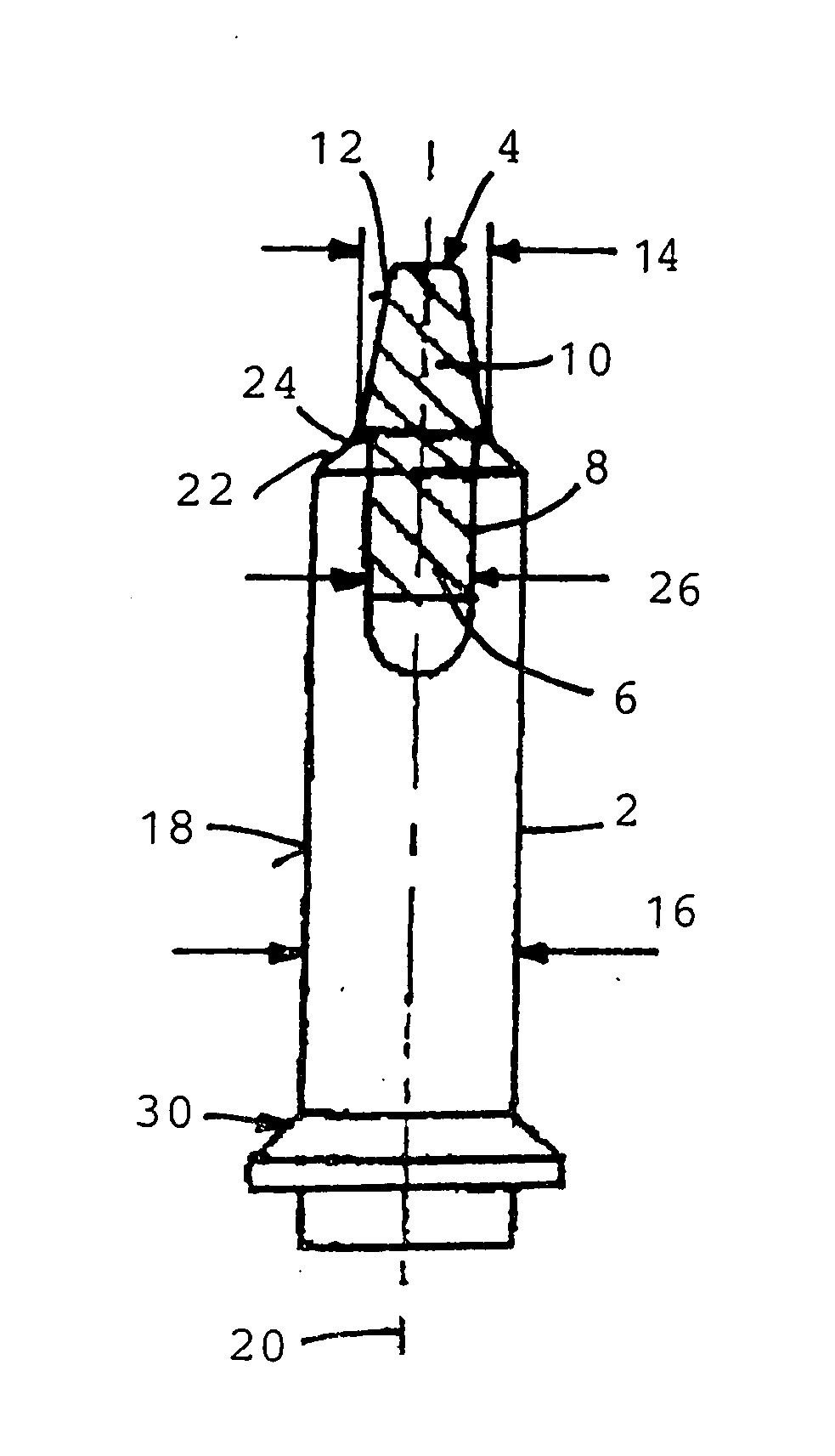
[0011] In accordance withFIG. 1, a receiving element comprises a bolt 2, and a tip 4 that is produced as a separate component having an end section 6 which engages in a recess 8 of the bolt 2 at a forward end of the latter. The bolt 2 comprises or contains wear-resistant sintered material, preferably oxide ceramics, such as, for example, Al2O3 or ZrO2, or non-oxide ceramics such as Si3N4, or mixtures thereof. The forward section 10 of the pin 4 projects axially out of the bolt 2 and presents an exterior surface 12 that is at least approximately and / or largely conical. In the exit area from the bolt 2, the tip 4 or the forward section 10 thereof includes a maximum external diameter 14 that is smaller by a prescribed amount than the external diameter 16 of the bolt 2 or the exterior surface 18 thereof. The recess 8 in the forward end of the bolt 2 is preferably embodied as a blind hole, and the end section 6 extends axially over only a fraction of the entire length of the bolt 2.

[001...


PUM


Abstract

A receiving element which can be introduced into a borehole of at least one component includes a bolt presenting an outer surface that is approximately parallel and advantageously coaxial to a longitudinal axis of the bolt. The receiving element requires few materials and can therefore be produced at a low constructional cost while being provided with high dimensional stability and positioning accuracy. The bold includes an abrasion-resistant sintered material, and a metal tip provided on the front end of the shaft. The end part of the tip is engageable in a recess of the bolt, and there is a direct connection between the end part and the recess in the connection region on the front end of the bolt.

Description

BACKGROUND OF THE INVENTION [0001] The invention relates to a receiving element useful, for example, as a centering pin or receiving pin for centering and receiving components, in particular a plurality of metal sheet parts or at least one metal sheet part having a threaded female element, and more particularly employable in association with welding tools, in particular pressure welding tools, apparatus or machines. [0002] A receiving element is disclosed in WO 2004 / 069 468 A1, having a bolt that, in the area of its external surface, which is largely parallel to a longitudinal axis, includes at least two recesses with apertures. Arranged in these recesses are pins that comprise or contain wear-resistant material and that extend somewhat radially through said apertures and project over the external surface with a predefined overhang. Such receiving elements can be introduced into bores of at least one component for fixing and / or aligning for subsequent machining. For instance, if two...

Claims


Application Information

Patent Timeline
Patent Type & Authority Applications(United States)
IPC IPC(8): F16B37/06F16B35/00B23Q3/18B23Q16/00F16B19/02F16B35/04
CPCB23Q16/001B23Q3/183Y10S411/90B23Q3/18B23Q16/00F16B19/02F16B35/04
Inventor SCHRAMM, PETER
Owner FRIATEC AG DE
Why Eureka
Try Eureka