Melt extruded fibers and methods of making the same
a technology of extruded fibers and melts, which is applied in the direction of spinnerette packs, natural mineral layered products, transportation and packaging, etc., can solve the problems of less economically viable processes, limited process pressure, and limited process temperature, so as to reduce the potential for fracture and poor tensile response of multiphase polymers.
- Summary
- Abstract
- Description
- Claims
- Application Information
AI Technical Summary
Benefits of technology
Problems solved by technology
Method used
Image
Examples
example 1
[0112] A polymeric fiber was produced using apparatus similar to that shown in FIG. 5. A single orifice die as shown in FIG. 6 was used. The die orifice was circular and had an entrance diameter of 1.68 mm, an exit diameter of 0.76 mm, a length of 12.7 mm and a semi-hyperbolic shape defined by the equation:
rz=[0.00140625 / ((0.625*z)+0.0625)]ˆ0.5 (9)
where z is the location along the axis of the orifice as measured from the entrance and rz is the radius at location z.
[0113] Polypropylene homopolymer (FINAPRO 5660, 9.0 MFI, Atofina Petrochemical Co., Houston, Tex.) was extruded with a 3.175 cm single screw extruder (30:1 L / D) using a barrel temperature profile of 177° C.-232° C.-246° C. and an in-line ZENITH gear pump (1.6 cubic centimeters / revolution (cc / rev)) set at 19.1 RPM. The die temperature and melt temperature were approximately 220° C. Chevron SUPERLA white mineral oil #31 as a lubricant was supplied to the entrance of the die using a second ZENITH gear pump (0.16 cc / rev) ...
example 2
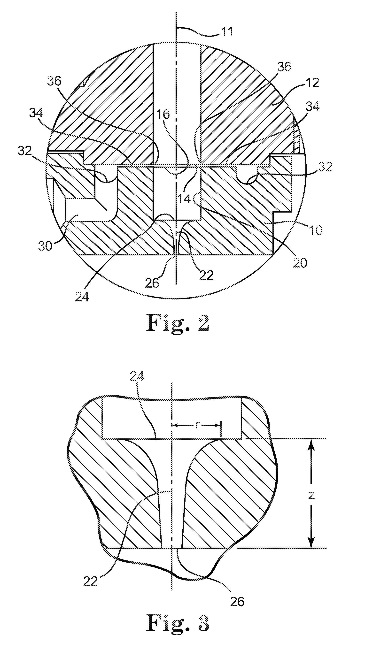
[0115] A polymeric fiber was produced as in Example 1 except that a die similar to that depicted in FIG. 2 was used. The die orifice had a circular profile with an entrance diameter of 6.35 mm, an exit diameter of 0.76 mm, a length of 10.16 mm and a semi-hyperbolic shape defined by Equation (8) as described herein.
[0116] Molten polymer pressure and mass flow rate of the extrudate are shown in Table 2 below with and without lubricant.
example 3
[0117] A polymeric fiber was produced as in Example 1 except that a die as shown in FIG. 2 was used. The die orifice had a circular profile with an entrance diameter of 6.35 mm, an exit diameter of 0.51 mm, a length of 12.7 mm and a semi-hyperbolic shape defined by Equation (8).
[0118] Polyurethane (PS440-200 Huntsman Chemical, Salt Lake City, Utah) was used to form the fiber. The polymer was delivered with a 3.81 cm single screw extruder (30:1 L / D) using a barrel temperature profile of 177° C.-232° C.-246° C. and an in-line ZENITH gear pump (1.6 cc / rev) set at 19.1 RPM. The die temperature and melt temperature was approximately 215° C. Chevron SUPERLA white mineral oil #31 as a lubricant was supplied to the entrance of the die via two gear pumps in series driven at 99 RPM and 77 RPM respectively. Molten polymer pressure and mass flow rate of the extrudate is shown in Table 1 below. A control sample was also run without the use of lubricant.
TABLE 2Melt PressureMass Flow RateExampl...
PUM
| Property | Measurement | Unit |
|---|---|---|
| Ra | aaaaa | aaaaa |
| Ra | aaaaa | aaaaa |
| root-mean-square roughness | aaaaa | aaaaa |
Abstract
Description
Claims
Application Information
 - R&D
- Intellectual Property
- Life Sciences
- Materials
- Tech Scout
- Unparalleled Data Quality
- Higher Quality Content
- 60% Fewer Hallucinations
Browse by: Latest US Patents, China's latest patents, Technical Efficacy Thesaurus, Application Domain, Technology Topic, Popular Technical Reports.
© 2025 PatSnap. All rights reserved.Legal|Privacy policy|Modern Slavery Act Transparency Statement|Sitemap|About US| Contact US: help@patsnap.com


