Interconnect structure between HyperTransport bus interface boards

a hyper-transit bus and interface board technology, applied in the direction of electric digital data processing, instruments, etc., can solve the problems of interconnection, difficult or impossible physical realization, intercrossing of signals on the bus, etc., and achieve the effect of increasing costs

Inactive Publication Date: 2007-07-05
HUAWEI TECH CO LTD
View PDF2 Cites 7 Cited by
  • Summary
  • Abstract
  • Description
  • Claims
  • Application Information

AI Technical Summary

Benefits of technology

[0012] The embodiments of the present invention provides an interconnect structure between HyperTransport boards, which is adapted for interconnecting the corresponding HyperTransport bus interfaces disposed on different Printed Circuit Boards (PCBs) via a connector; it is different from the prior art in that the connector according to the embodiments of the present invention cuts across the HyperTransp

Problems solved by technology

In a certain case, such an interconnection will cause the intercrossing of the signals on the bus.
Such an interconnection is very difficult for the design of an inter-board connector.
Such an intercrossing problem is caused by the positions of the devices, the distribution of encapsulation pins of the devices and the PCB connection mode.
Those signals may be interconnected via cross-connected connectors, which is difficult or impossible to realize physically.
However, such a scheme is inhibited for a HyperTransport bus.
Another solution is to

Method used


Image

  • Interconnect structure between HyperTransport bus interface boards
  • Interconnect structure between HyperTransport bus interface boards
  • Interconnect structure between HyperTransport bus interface boards

Examples


Embodiment Construction

[0020] The structure and features of the present invention will become more apparent by the following description in detail with reference to the embodiments and the accompanying drawings.

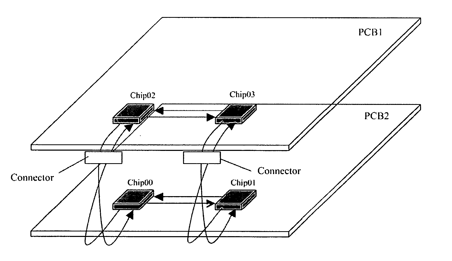
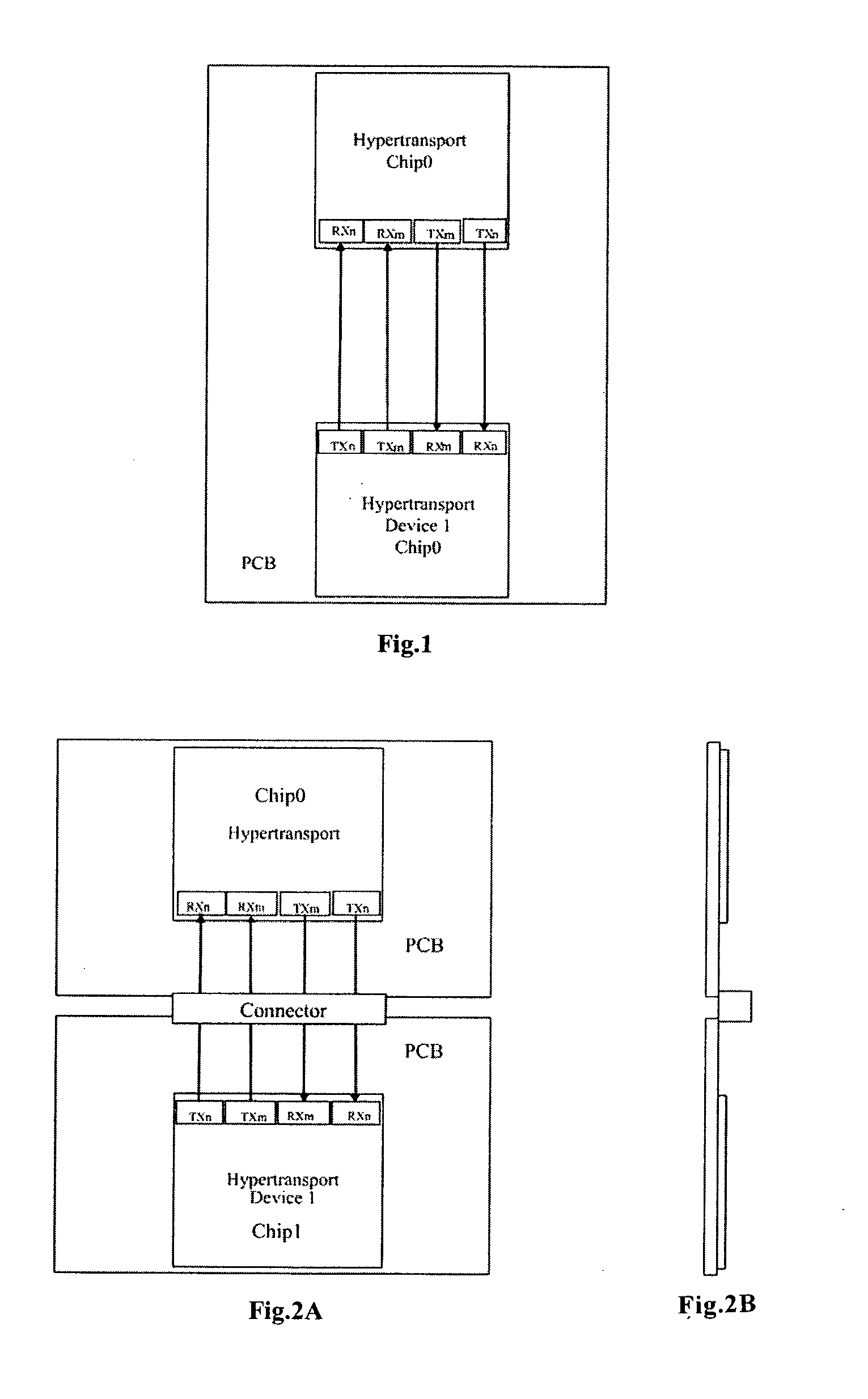
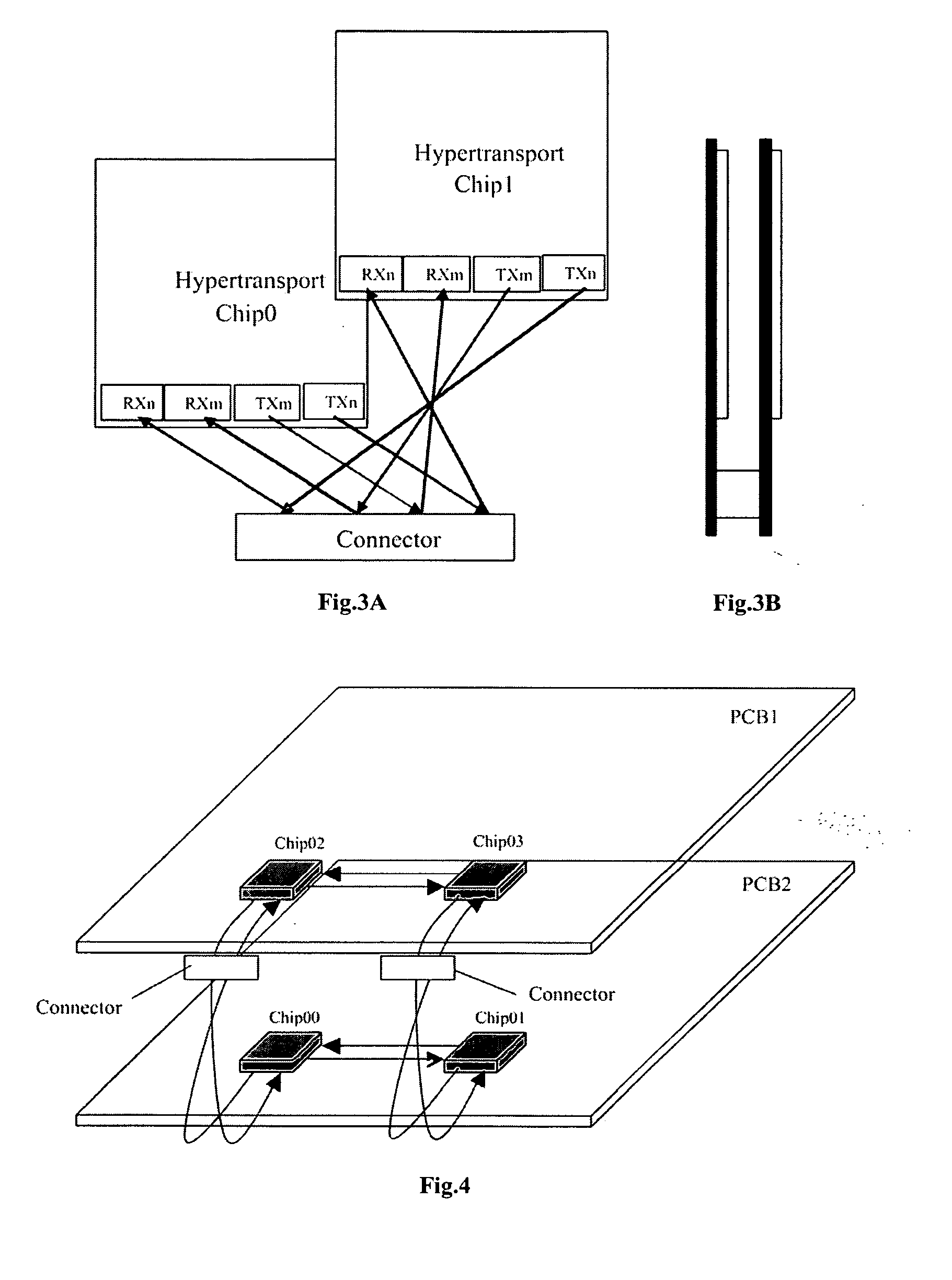
[0021] According to the interconnect structure between HyperTransport bus interface boards of an embodiment of the invention, the corresponding HyperTransport bus interfaces disposed on different PCBs are interconnected via a connector; it is different from the prior art in that the connector according to the embodiments of the present invention cuts across the HyperTransport bus. Thus, the signals on the HyperTransport bus between the PCBs will not intercross.

[0022] It is noted that in practice one or multiple connectors may be utilized.

[0023] When multiple connectors are used, the multiple connectors may be arranged in the following three modes:

[0024] (1) The multiple connectors are disposed collinearly in the longitudinal direction of the connectors;

[0025] (2) The multiple connectors are di...


PUM


Abstract

An interconnect structure between HyperTransport bus interface boards, for interconnecting corresponding HyperTransport bus interfaces disposed on different Printed Circuit Boards (PCBs) via a connector. The connector cuts across a HyperTransport bus, and terminals of two HyperTransport bus interfaces on different PCBs connected via the connector are connected with each other correspondingly via connecting lines sequentially distributed, so as to avoid the intercross of the connecting lines. The present invention may solve the problem of intercrossing of signals on the HyperTransport bus between processors or other chips during inter-board connecting without the increase of PCB layer number or the degradation of signal quality and the additional cost.

Description

FIELD OF THE INVENTION [0001] The present invention relates to the technical field of electronic or communication equipment manufacturing, in particular, to an interconnect structure between HyperTransport bus interface boards. BACKGROUND OF THE INVENTION [0002] HyperTransport is an end-to-end bus technology designed for the integrated circuit interconnection on a motherboard. It can provide higher data transmission bandwidth between a memory controller, a disk controller and a PCI bus controller. HyperTransport technology helps reduce the number of buses in a system and provide high-performance data transmission scheme for embedded applications. For example, HyperTransport technology may provide a high-level end-to-end internal connection standard to meet the data transmission requirement of a memory and an I / O element, and may be utilized to connect conventional low speed I / O devices and high speed I / O media. HyperTransport technology allows chips inside of PCs, network and commun...

Claims


Application Information

Patent Timeline
IPC IPC(8): G06F13/00
CPCG06F13/409
Inventor WU, MANBOHUANG, YINGDONGLIU, CHAOLI, ZHENHONG
Owner HUAWEI TECH CO LTD
Why Eureka
Try Eureka