Process for use with dual-fuel systems

a dual-fuel and process technology, applied in the field of dual-fuel engine systems, can solve the problems of low engine load, low engine efficiency, and inability to achieve the thermal energy (i.e., btus) required to maintain a desired power, and achieve the effects of reducing the utilization of diesel fuel, reducing the emissions of diesel engines, and minimizing the use of diesel fuel

Inactive Publication Date: 2007-07-12
TGI
View PDF20 Cites 54 Cited by
  • Summary
  • Abstract
  • Description
  • Claims
  • Application Information

AI Technical Summary

Benefits of technology

[0012] Accordingly, the inventors have recognized that additional or alternate means for metering the volume of a gaseous-fuel flow in order to fine-tune that flow volume may, in many instances, be desirable. In this regard, it has been determined that by monitoring one or more engine parameters such as, for example, exhaust gas temperature, exhaust oxygen levels, and / or engine speed, the flow volume of the gaseous-fuel may be adjusted (i.e., in conjunction with or independent of load based metering) to prevent loss of power at high-end loads while maintaining favorable emission outputs over substantially the entire operating range of the engine.
[0040] In any of the above aspects, the emissions of a diesel engine may be significantly reduced without affecting the power output of that engine. This is due in part to more complete combustion of diesel fuel within the engine due to the inclusion of the gaseous-fuel as well as the reduction of diesel fuel utilized by the engine. Of note, any gaseous fuel may be utilized including, without limitation, natural gas, methane, propane, hydrogen, vaporized ethanol, vaporized methanol, and / or any other gas or vapor having adequate combustion properties. Further, it will be noted that the above-noted fumigation systems may be set to minimize the diesel fuel utilized by an engine. This has significant benefits in natural gas and / or methane gas well production applications. In such applications, natural gas engines or diesel are often utilized for pumping and / or compressing gas from wells into pipelines. Due to the low BTU value of the natural gas, such natural gas engines are often considerably larger and more expensive than a diesel engine having a similar power rating. In this regard, it is desirable to utilize diesel engines though these diesel engines may be remotely located and require frequent servicing (e.g., replenishment of diesel fuel). By incorporating a fumigation system onto these remotely located engines such that they utilize gaseous-fuel, of which there is a ready supply, the rate of diesel usage may be significantly reduced thereby lowering the service requirement of such engines.

Problems solved by technology

The first disadvantage is typically encountered at high load operating conditions when elevated temperature and pressure in the engine during the compression strokes makes the intake air / gaseous-fuel mixture susceptible to premature detonation or knocking.
Furthermore, at such high loads, some gaseous-fuels (e.g., natural gas) lack the thermal energy (i.e., BTUs) required to maintain a desired power output of the engine.
The second disadvantage is encountered at low engine load where the gaseous-fuel and air mixture may be too lean for satisfactory combustion.
In this instance, fuel consumption may actually increase, as may the emissions of hydrocarbons (i.e., unburned gaseous-fuels) and particulates.
Both of the above noted disadvantages are particularly acute in diesel engines, which run at varying load levels during operation (e.g., on-road and off-road vehicles).
However, in this method no gaseous-fuel is supplied at low load levels (e.g., idle) as no boost pressure is generated at such load levels.
Therefore, the system fails to provide any emissions benefits at low load levels.
Furthermore, at high load levels, where the boost pressure may fully open such a valve, excess gaseous-fuel may flow into the intake air stream, which may result in knocking and / or lowered engine performance.
In this regard, strict load-based metering is often, by itself, inadequate for diesel engines that experience varying load levels.

Method used


Image

  • Process for use with dual-fuel systems
  • Process for use with dual-fuel systems
  • Process for use with dual-fuel systems

Examples


first embodiment

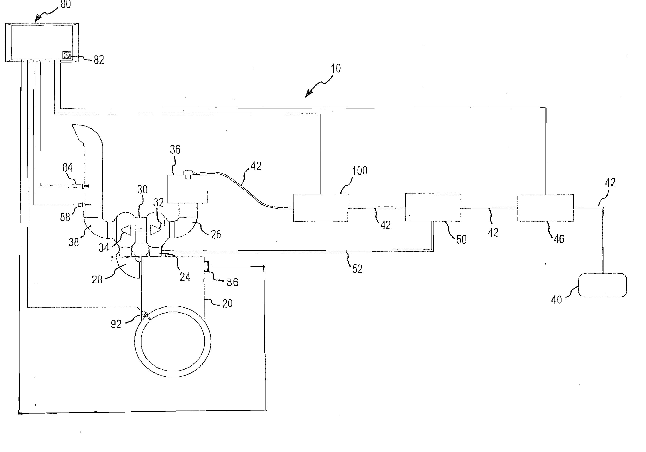
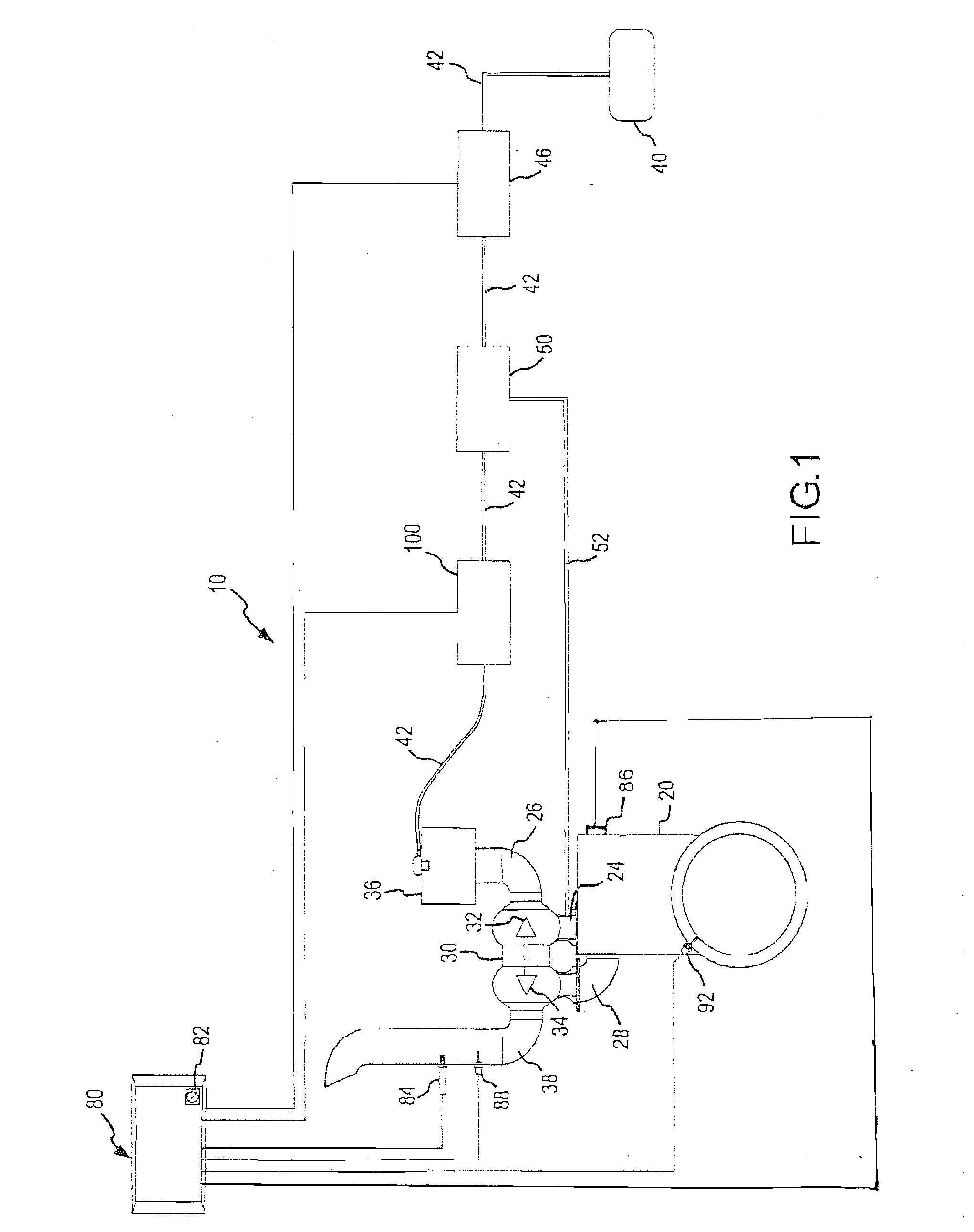
[0048] The present invention will now be discussed in relation to the accompanying drawings, which at least partially assist in illustrating its various pertinent features. FIG. 1 shows a schematic view of a dual-fuel fumigation system 10 interconnected to a turbocharged diesel engine 20. The fumigation system 10 is applicable to a variety of diesel engine applications and may be utilized in any of a variety of environments where diesel engines are utilized. For example, the fumigation system 10 may be utilized with stationary power generation systems as well as on-road and off-road diesel powered vehicles. That is, the system may be utilized with diesel engines designed to operate at a set load level as well as with diesel engines having varying load requirements due to, for example, idling needs, acceleration needs, cruising needs, etc. Furthermore, it will be noted that the fumigation system 10 is discussed in relation to its applicability to turbocharged diesel engines, however,...

second embodiment

[0072]FIG. 5 shows another embodiment of the gaseous-fuel fumigation system 10. As shown, the second embodiment does not utilize the lock-off valve 46 or the boost-pressure valve 50. Rather, the system of FIG. 5 relies upon a single ECU controlled valve 200 to regulate the flow between the gas supply 40 and the air intake 36. Of note, in FIG. 5 the gas supply 40 is received from a gas well 44. In this regard, it will be appreciated the in the production of natural and methane gas, diesel engines are commonly utilized for pumping and compressing gas from wells into pipelines. In this regard, these diesel engines have a ready supply of natural gas that may be utilized with the above-noted systems. However, it will be appreciated that gas received from the well 44 may require dehydration and / or compression prior to use with the diesel engine 20. It will be further appreciated that the system of FIG. 5 may be utilized with other gas sources.

[0073] The dual-fuel fumigation system 10, as ...


PUM


Abstract

A system and method is provided for use with a duel-fuel fumigation system. The system injects a gaseous-fuel flow into the air intake stream of a diesel engine. As presented, the system is operative to meter the gaseous-fuel flow into the diesel engine based on one or more engine parameters such as, for example, exhaust gas temperature, exhaust oxygen levels, engine speed, engine load and / or engine inlet pressure. Monitoring one or more engine parameters allows fine-tuning the flow of gaseous fuel into the engine and thereby prevents loss of engine power at high-end loads while maintaining favorable emission outputs over substantially the entire operating range of the engine.

Description

CROSS REFERENCE TO RELATED APPLICATIONS [0001] This application is a continuation in part of U.S. patent application Ser. No. 11 / 099,726 filed on Apr. 4, 2005, which is a continuation of U.S. patent application Ser. No. 10 / 797,803 filed on Mar. 10, 2004, now U.S. Pat. No. 6,901,889.FIELD OF THE INVENTION [0002] The present invention relates generally to duel-fuel engine systems. More particularly, the present invention relates to a fumigation system for controlling the injection of a gaseous-fuel into an air intake of a diesel engine. BACKGROUND [0003] Due to the high thermal efficiency achieved by compression-ignited engines (e.g., in comparison with spark-ignited engines), such engines are commonly utilized in industrial applications. Further, due to increasing fuel costs, such engines are also gaining popularity in the passenger vehicle and light truck markets. The high efficiency of compression-ignited engines, such as diesel engines, is due in part to the ability to use higher ...

Claims


Application Information

Patent Timeline
Patent Type & Authority Applications(United States)
IPC IPC(8): F02D41/00F02M21/02
CPCF02B23/0621F02B29/0418F02D15/04F02D19/0631F02D19/066F02D19/105F02D35/027Y02T10/146Y02T10/36Y02T10/32F02D19/0644F02D19/0655F02M21/0239Y02T10/12Y02T10/30
Inventor RITTER, GREGORY W.JONES, TERRY A.
Owner TGI
Why Eureka
Try Eureka