
Silicon dot forming method and apparatus

a technology of silicon dots and forming methods, applied in the direction of transportation and packaging, nuclear engineering, railway signalling, etc., can solve the problems of difficult uniformization of difficulty in uniformizing particle diameters and density distribution of silicon dots

Inactive Publication Date: 2007-07-12
NISSIN ELECTRIC CO LTD
View PDF9 Cites 18 Cited by
  • Summary
  • Abstract
  • Description
  • Claims
  • Application Information

AI Technical Summary

Benefits of technology

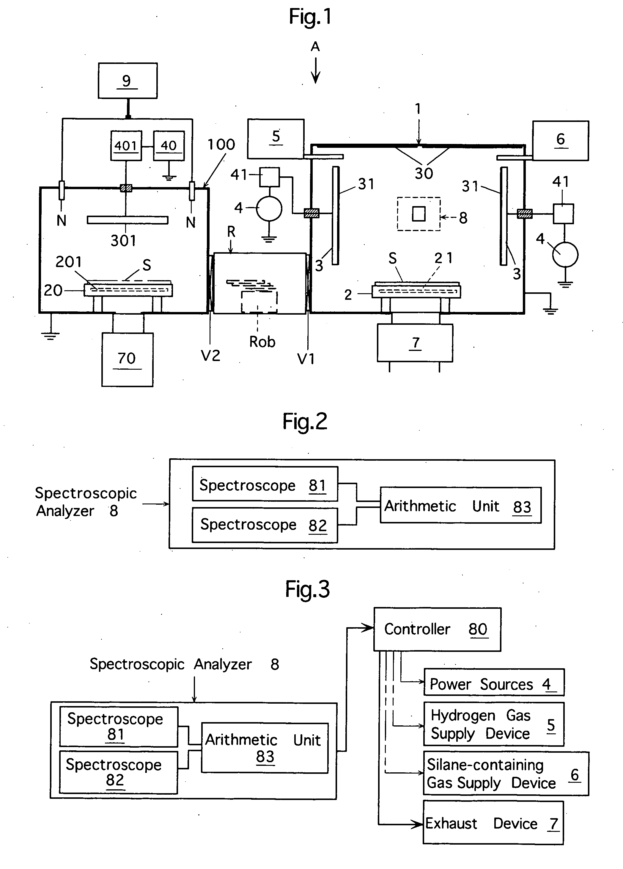
[0015] An object of the invention is to provide a method in which silicon dots having substantially uniform particle diameters and exhibiting a substantially uniform density distribution are formed directly on a silicon dot formation target substrate at a low temperature as compared with the conventional CVD methods, and terminally treated silicon dots can be easily obtained from the silicon dots.
[0016] Also, it is an object of the invention to provide a silicon dot forming apparatus by which silicon dots having substantially uniform particle diameters and exhibiting a substantially uniform density distribution can be formed directly on a silicon dot formation target substrate at a low temperature as compared with the conventional CVD methods, and terminally treated silicon dots can be easily obtained from the silicon dots.
[0026] Silicon dots terminally treated with oxygen or nitrogen can be easily obtained by exposing the silicon dots thus formed to a plasma produced from an oxygen-containing gas and / or nitrogen-containing gas. [Silicon Dot Forming Method]

Problems solved by technology

However, among conventional silicon dot forming methods, the method involving heating and vaporizing the silicon by laser irradiation can not uniformly control an energy density for irradiating the silicon with the laser, and therefore it is difficult to uniformize the particle diameters and density distribution of silicon dots.
In the in-gas vaporizing method, the silicon is heated nonuniformly, and therefore the particle diameters and the density distribution of silicon dots are difficult to uniformize.

Method used


Image

  • Silicon dot forming method and apparatus
  • Silicon dot forming method and apparatus
  • Silicon dot forming method and apparatus

Examples


Embodiment Construction

[1] Concerning the Silicon Dot Forming Method

[0094] Preferred embodiments of the silicon dot forming method according to the invention are roughly classified into the following two types.

[0095] A silicon dot forming method including:

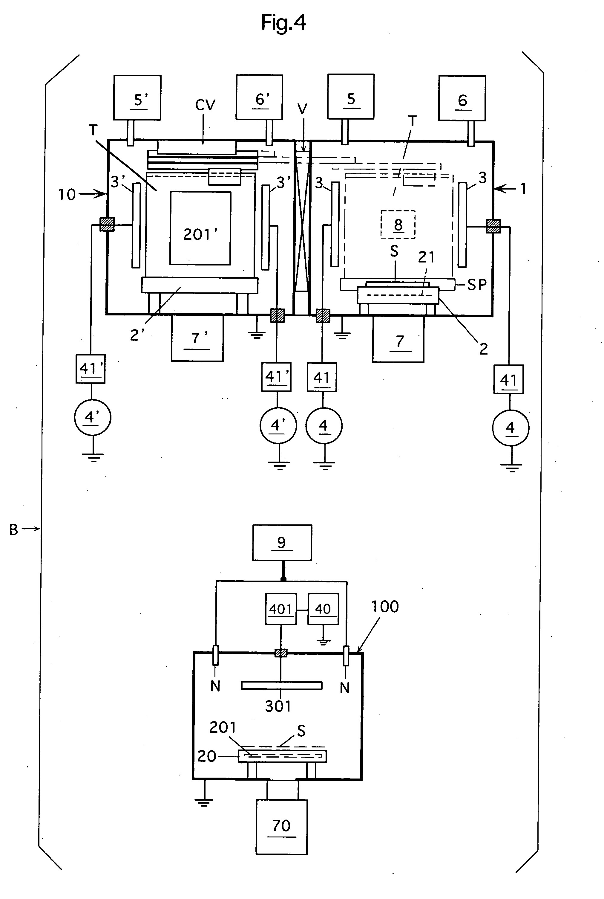
[0096] a step of arranging a silicon sputter target in a silicon dot forming chamber; a silicon dot forming step of arranging a silicon dot formation target substrate in the silicon dot forming chamber, supplying a sputtering gas into the chamber, applying a high-frequency power to the gas to generate plasma for sputtering in the chamber, and forming silicon dots on the silicon dot formation target substrate by effecting chemical sputtering on the silicon sputter target with the plasma; and

[0097] a terminally treating step of arranging in a terminally treating chamber the substrate having the silicon dots formed thereon by the silicon dot forming step, supplying into the terminally treating chamber at least one terminally treating gas selected from a...


PUM

PropertyMeasurementUnit
Nanoscale particle sizeaaaaaaaaaa
Frequencyaaaaaaaaaa

Abstract

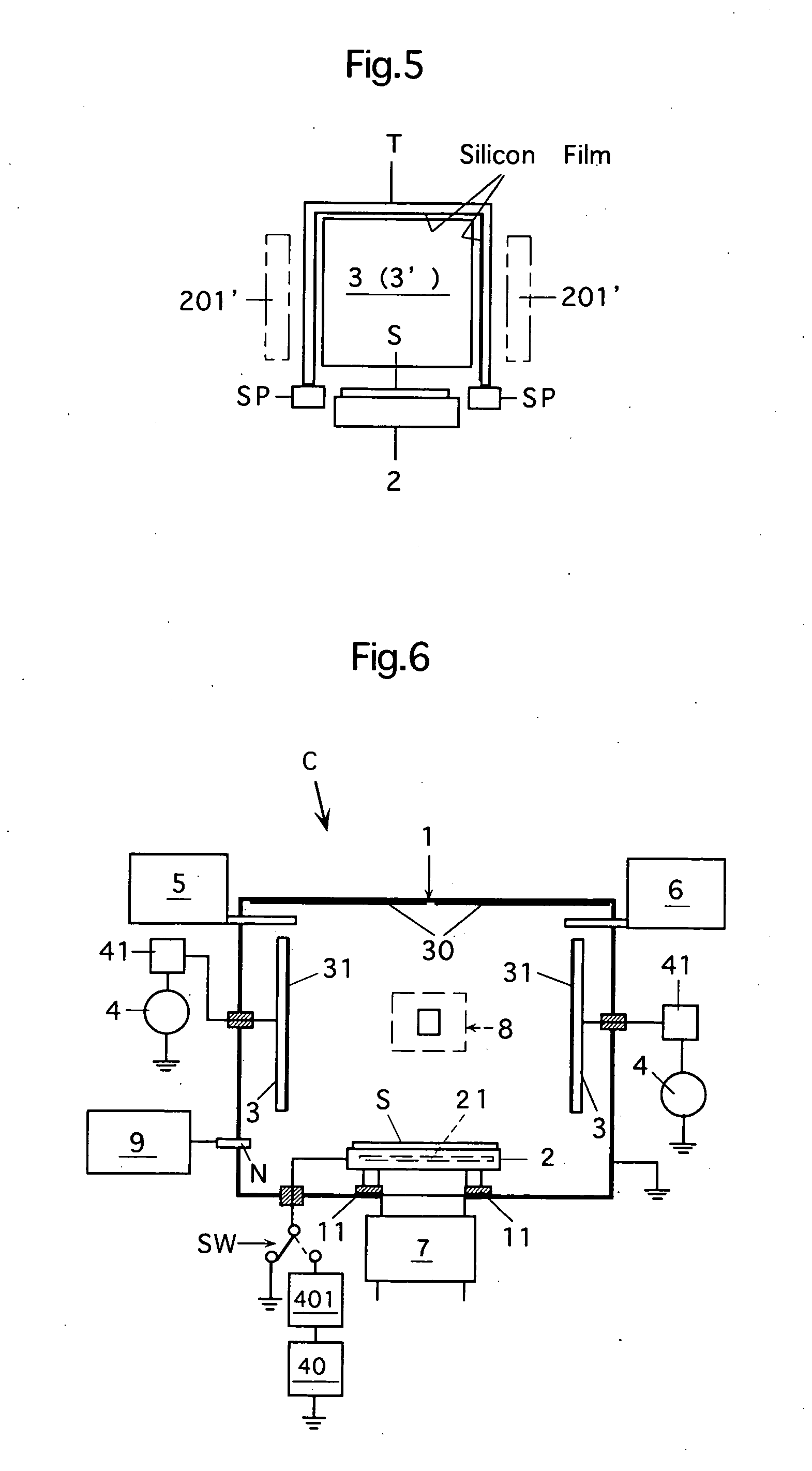
A silicon sputter target is arranged in a silicon dot forming chamber, and a silicon dot formation target substrate is arranged in the chamber. Plasma is formed from a sputtering gas (typically a hydrogen gas) supplied into the chamber, and chemical sputtering is effected on the target with the plasma thus formed to form silicon dots on the substrate S. Optionally, with the plasma formed from a hydrogen gas and a silane-containing gas at a plasma emission intensity ratio (Si(288 nm) / Hβ) of 10.0 or lower, the silicon dots are formed on the substrate S. The silicon dots are terminally treated with the plasma derived from a terminally treating gas such as an oxygen gas.

Description

CROSS REFERENCE TO RELATED APPLICATION [0001] This invention is based on Japanese Patent Application No. 2005-277031 filed in Japan on Sep. 26, 2005, the entire content of which is hereby incorporated by reference. BACKGROUND OF THE INVENTION [0002] 1. Field of the Invention [0003] The present invention relates to a method and an apparatus for forming silicon dots (i.e., so-called silicon nanoparticles) of minute sizes that can be used as electronic device materials for single-electron devices and the like, and light emission materials and others. [0004] 2. Description of the Related Art [0005] As a method of forming silicon nanoparticles, such a physical manner has been known that silicon is heated and vaporized in an inert gas by excimer laser or the like, and also an in-gas vaporizing method is known (see Kanagawa-ken Sangyo Gijutu Sougou Kenkyusho Research Report No. 9 / 2003, pp 77-78). The latter method is configured to heat and vaporize the silicon by high-frequency induction h...

Claims


Application Information

Patent Timeline
IPC IPC(8): C08J7/18C23C14/00C23C16/00
CPCC23C14/0057C23C14/04C23C14/5806C23C14/54C23C14/165
Inventor TAKAHASHI, EIJITOMYO, ATSUSHI
Owner NISSIN ELECTRIC CO LTD
Learn More