
High-speed jet control

a jet control and high-speed technology, applied in the direction of coatings, lighting and heating apparatuses, combustion types, etc., can solve the problems of difficult to coat evenly in this manner, difficult to control the speed of the jet, so as to improve the flame spray process, reduce the temperature, and increase the effect of heat dissipation

Inactive Publication Date: 2007-07-12
UTAH STATE UNIVERSITY
View PDF6 Cites 4 Cited by
  • Summary
  • Abstract
  • Description
  • Claims
  • Application Information

AI Technical Summary

Benefits of technology

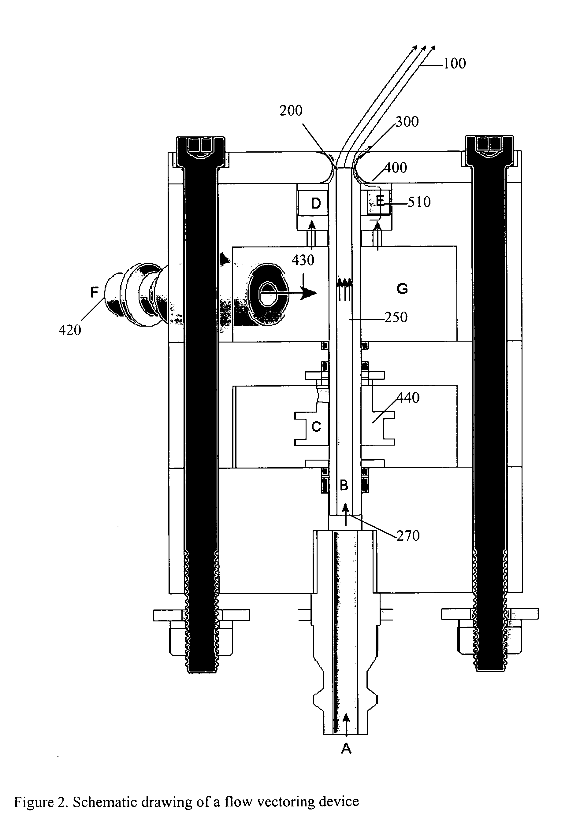
[0011] A new device is disclosed that uses a flow-control methodology to control the direction and profile of high-speed jets or sprays at very high precision and frequency. The device is based on an enhanced Coanda effect. The device will make it possible to control flow in harsh environments and to apply thin films to very large surface areas with a single nozzle, and to do so to a precisely desired thickness.
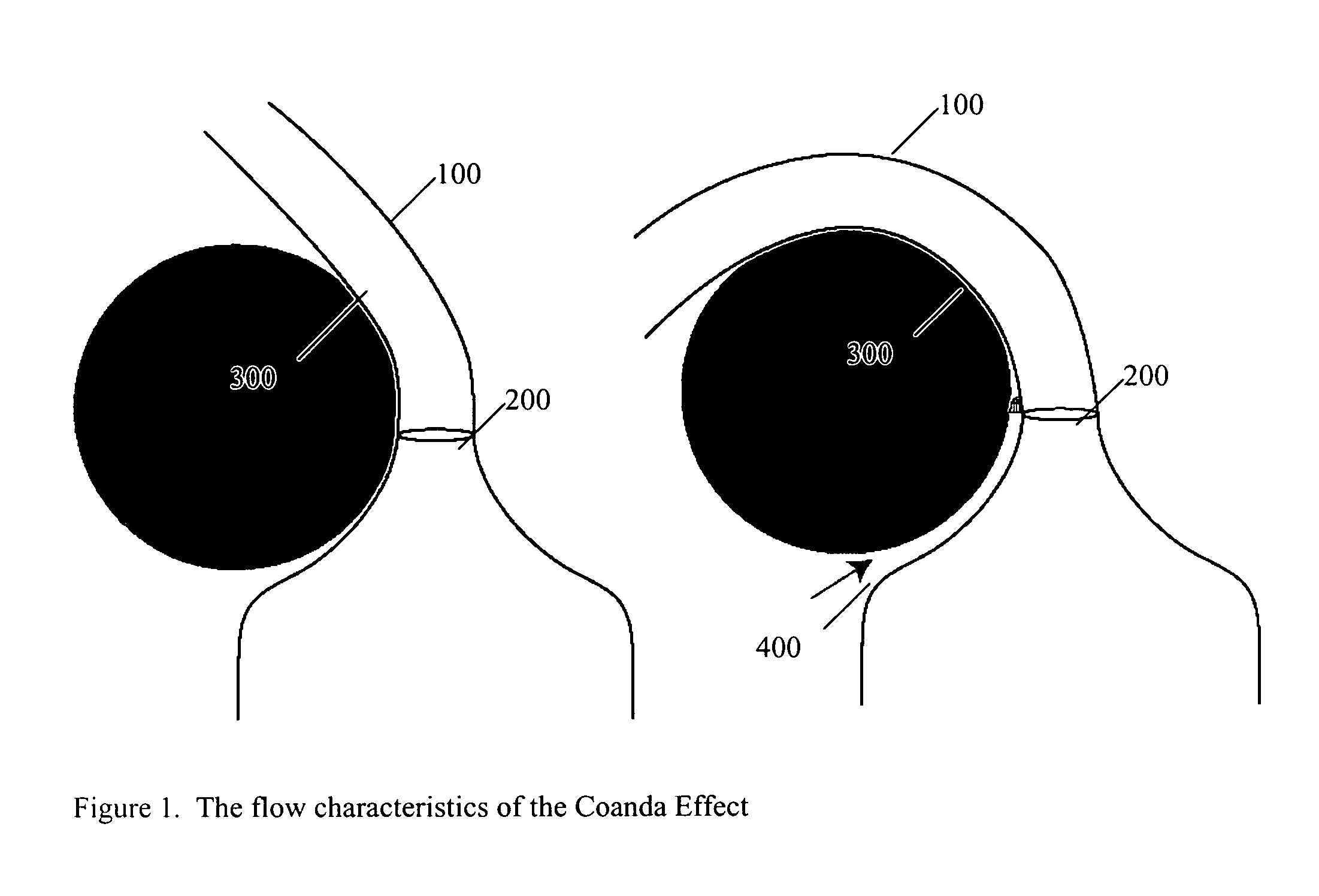
[0012] This device makes use of an enhanced Coanda effect, termed Coanda assisted Spray Manipulation (CSM), to vector and control the profile (width) of the jet. The Coanda effect, or the tendency of jets to adhere to nearby surfaces, is a well established flow-control methodology. Flow-control is achieved by adding a blowing control flow to enhance profile and direction control and improve the stability of the jet or spray. This device makes it possible to apply films on large surfaces at precisely controllable thicknesses with a single nozzle and no moving parts in or near the jet flow (where corrosive materials, combustion and / or high temperatures may be present). As such, the new device will enable long-term operation of controllable jets or sprays in harsh, corrosive, and combusting environments.
[0014] CSM can improve flame spray processes by rapidly orbiting the flame at rates above the response time of the particulate material. By orbiting the flame, the intense heating of the substrate that is typical of flame sprays is mitigated. The heat is spread to a much larger area resulting in lower temperatures.

Problems solved by technology

In many of these processes, Such as Thermal sprays, the contents of the jet or spray are combusting, making the environment in which the jet operates very hostile.
Control schemes that rely on vectoring of the jet nozzle would place moving parts in this hostile environment, where they would wear quickly, and be severely limited in slew rate.
Additionally, it is difficult to coat evenly in this manner.
The hardware required to effect these changes is unreliable and heavy and thus slow.
However, it is difficult to reliably generate the required oscillatory blowing.
Currently, expensive robots are commonly used for this purpose.
Thermal spray processes typically result in very high material cooling rates (>106 K / s).
Due to the high temperature combustion environment present in or near these process nozzles, mechanical vectoring of the nozzle is not feasible since this would place moving parts in the jet flow, reduce device durability, and severely limit directional frequency response.
Furthermore, traversing a part to be coated, which is often heated to high temperatures, is costly.
This results in excessive heating of the substrate.
This is currently being investigated as a method for thrust-vectoring of fighter aircraft, although the hardware required to effect these changes is unreliable and heavy (and thus slow).
However, it is difficult to reliably generate the required oscillatory blowing.
Unfortunately, schemes involving suction prohibit use in hostile environments such as combustion since hot and / or corrosive gas would be drawn into the suction slot.

Method used


Image

  • High-speed jet control
  • High-speed jet control
  • High-speed jet control

Examples


Embodiment Construction

[0031] This disclosure presents a new device that uses a flow-control methodology to control sprays at very high precision and frequency. The device has several applications, for example it will make it possible to apply thin films to very large surface areas with a single nozzle, and to the so to a precisely desired thickness.

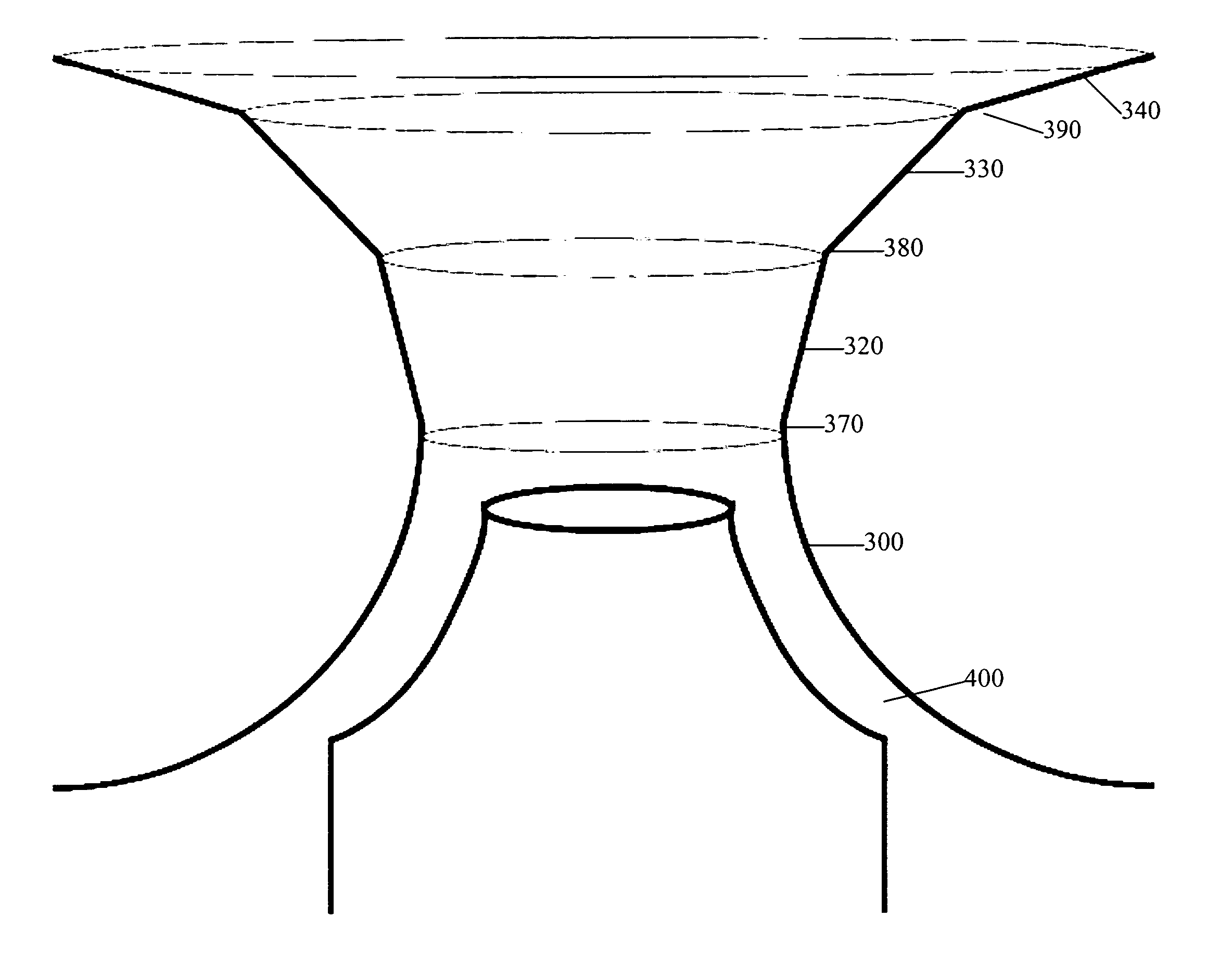
[0032] The Coanda effect, also known as “boundary-layer attachment”, is the tendency of a stream of fluid 100 to stay attached to a convex surface 300, rather than follow a straight line in its original direction. The principle was named after Romanian inventor Henri Coand{hacek over (a)}, who was the first to understand the practical importance of the phenomenon for aircraft development. The Coanda effect results form the reduced pressure on the inside of the turning radius. This competes with the dissipation of the boundary-layer energy until the flow detaches from the surface. The jet is simply turned and nominally retains the same cross-section dimension....


PUM

PropertyMeasurementUnit
vectoring anglesaaaaaaaaaa
Speedaaaaaaaaaa
speedaaaaaaaaaa

Abstract

A device is disclosed that uses a flow-control methodology to control sprays at very high precision and frequency. The device is based on an enhanced Coanda effect. The control flow is selectively applied to the region in which we desire the jet to vector and control the profile (width) of the jet. In one embodiment, the control flow is applied at the desired circumferential location by the action of a rotting disk with a flow passage of a size that spreads the jet the desired amount. The size of this flow passage may be controlled by using two overlapping disks with large holes in each. By rotating one disk relative to the other, the size of the resultant passage can be modified.

Description

RELATED APPLICATIONS [0001] This application claims priority to U.S. patent application Ser. No. 60 / 749,202 filed on Dec. 9, 2005, entitled “High-Speed Jet Control”, and is incorporated herein by reference.TECHNICAL FIELD [0002] This present invention relates to methods and devices for directing and controlling high-speed fluid jets and thermal sprays. BACKGROUND [0003] There are many processes that can benefit from the ability to precisely vector a jet and to control its width. These include thin-film coating processes in which it is vitally important that the film thickness be uniform, even if the surface to be coated is not flat. In many of these processes, Such as Thermal sprays, the contents of the jet or spray are combusting, making the environment in which the jet operates very hostile. Control schemes that rely on vectoring of the jet nozzle would place moving parts in this hostile environment, where they would wear quickly, and be severely limited in slew rate. Multiple noz...

Claims


Application Information

Patent Timeline
Patent Type & Authority Applications(United States)
IPC IPC(8): F23D11/10
CPCB05B1/12B05B3/02B05B7/0466B05B7/066B05B7/08Y10S239/07B05B7/205F23D14/48F23D2900/14481C23C4/12C23C24/04B05B7/0815B05B1/08
Inventor SMITH, BARTON L.
Owner UTAH STATE UNIVERSITY
Learn More