Collector in microwave tube

a technology of microwave tubes and collectors, applied in the direction of travelling-wave tubes, electric discharge tubes, electrical apparatus, etc., can solve the problems of reducing the withstand voltage, affecting the withstand voltage, and exposing the collector electrode to an immense amount of heat, so as to prevent a degradation of the withstand voltage

Inactive Publication Date: 2007-07-12
NEC MICROWAVE TUBE
View PDF2 Cites 6 Cited by
  • Summary
  • Abstract
  • Description
  • Claims
  • Application Information

AI Technical Summary

Benefits of technology

[0023]It is therefore an object of the present invention to provide a collector in a

Problems solved by technology

Therefore, the collector electrode is subjected to an immense amount of heat and is applied with a high voltage.
Therefore, the aforementioned displacement of the heat source in collector electrodes 41 would cause an associated shift of insulator 42 in the axial direction of the tube, resulting in a shorter cr

Method used


Image

  • Collector in microwave tube
  • Collector in microwave tube
  • Collector in microwave tube

Examples


Embodiment Construction

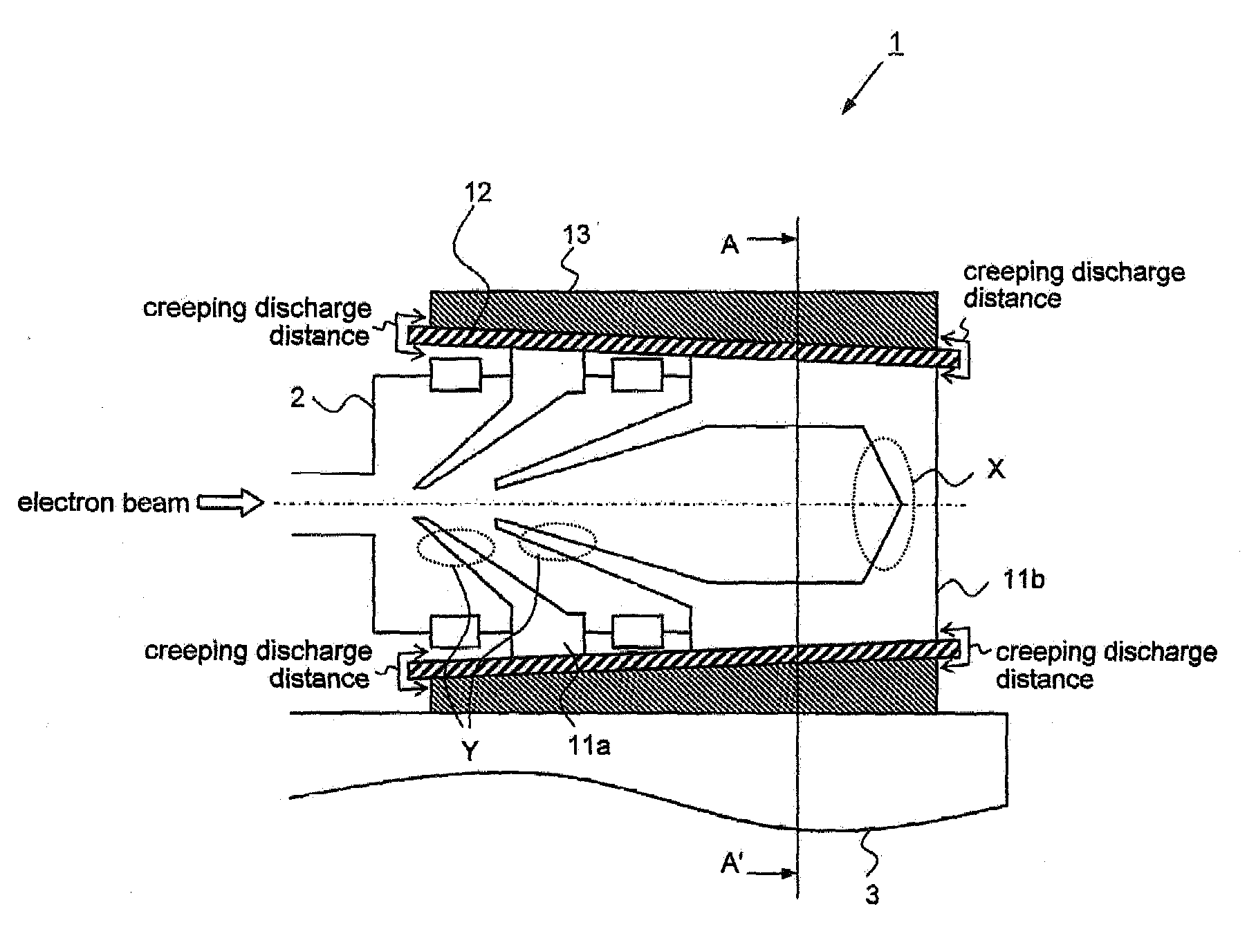
[0034]FIG. 3A is a longitudinal sectional view illustrating the structure of a collector in a microwave tube according to one embodiment of the present invention, and FIG. 3B is a cross-sectional view taken along line A-A′ in FIG. 3A. In FIGS. 3A and 3B, components identical to those in FIGS. 2A and 2B are designated the same reference numerals.

[0035]Referring to FIGS. 3A and 3B, collector 1 in the microwave tube according to this embodiment comprises collector electrodes 11 (collector electrodes 11a, 11b in the figures), insulator 12, and radiator 13. In collector 1, insulator 12 which covers collector electrode 11 has a conical configuration which is tapered in the axial direction of the tube.

[0036]As in a conventional collector, the creeping discharge distance of insulator 12 protruding from the creepage surface of each collector electrode 11 is reduced within an allowable range in collector 1, as well, in order to completely cover collector electrodes 11 with insulator 12.

[0037]...


PUM


Abstract

A collector in a microwave tube has a collector electrode for capturing an electron beam radiated from an electron gun and passing through a slow wave circuit, an insulator disposed in contact with the outer peripheral surface of the collector electrode, and a radiator disposed in contact with the outer peripheral surface of the insulator, wherein the insulator, the outer diameter of the collector electrode, and the inner diameter of the radiator are tapered in the axial direction of the tube.

Description

[0001]This application is based upon and claims the benefit of priority from Japanese Patent Application No. 2006-003744 filed on Jan. 11, 2006, the content of which is incorporated by reference.BACKGROUND OF THE INVENTION [0002]1. Field of the Invention:[0003]The present invention relates to a collector in a microwave tube for capturing an electron beam radiated from an electron gun and passing through a slow wave circuit.[0004]2. Description of the Related Art:[0005]FIG. 1 is a cross-sectional view illustrating the structure of a general microwave tube.[0006]Referring to FIG. 1, the general microwave tube comprises electron gun 51 for emitting an electron beam, slow wave circuit 52 for handling interaction between an RF signal (microwave) applied thereto and the electron beam emitted from electron gun 51 for amplification to deliver the amplified electron beam therefrom, collector 53 for capturing the electron beam which has passed through slow wave circuit 52, and anode electrode...

Claims


Application Information

Patent Timeline
IPC IPC(8): H01J25/34
CPCH01J25/34H01J23/027
Inventor TSUCHIDA, HIROSHI
Owner NEC MICROWAVE TUBE
Why Eureka
Try Eureka