Transmission line pulse measurement system for measuring the response of a device under test

a technology of transceiver pulse and response, which is applied in the direction of measurement devices, resistance/reactance/impedence, instruments, etc., can solve the problems of insufficient signal-to-noise ratio for some applications, short time skew, and incident and reflected pulse time delay, etc., to achieve the effect of improving the signal-to-noise ratio of measuremen

Inactive Publication Date: 2007-07-12
THERMO KEYTEK LLC
View PDF7 Cites 35 Cited by
  • Summary
  • Abstract
  • Description
  • Claims
  • Application Information

AI Technical Summary

Benefits of technology

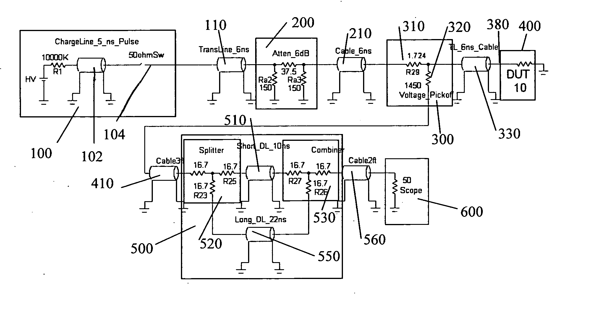
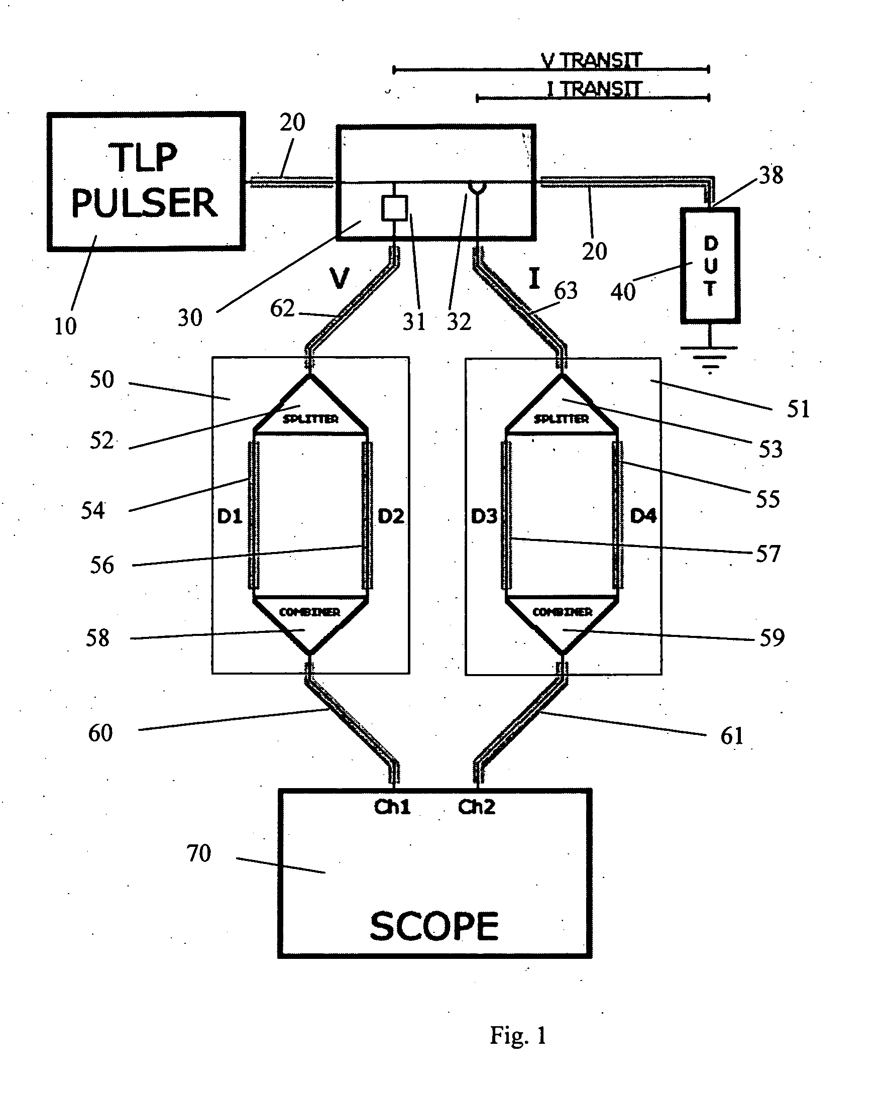
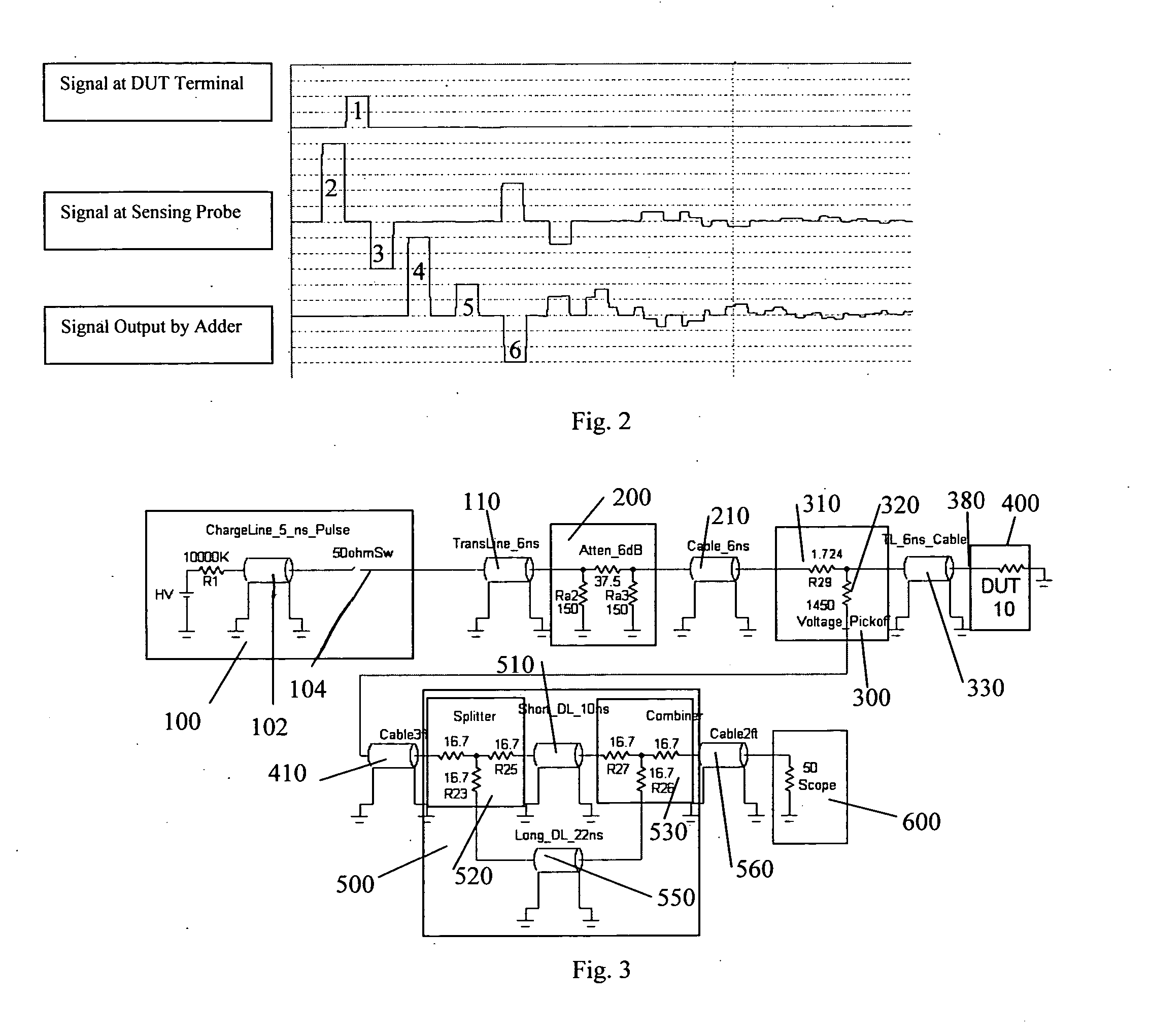
[0016] Accordingly, it is an object of the present invention to provide improved TLP systems for testing ICs and other devices, especially where there are ESD protection structures in such electronic parts. This invention is a TLP system that measures the current and / or voltage at a DUT terminal due to a pulse delivered through a constant impedance cable or a combination of cable and printed wiring board and measured at points within this constant impedance conduction path in a manner that compensates for the pulse delay caused by the travel time of the pulse from the measurement points to the DUT and back. In addition the new TLP system may include a high-speed oscilloscope and computer with gain optimizing software to improve the measurement's signal-to-noise ratio.

Problems solved by technology

Additionally, there are also signal measurement techniques well known in the art that improve the accuracy of such measurements but they can only be applied when the pulses overlap.
It is known in the art that the actual pulse at the DUT terminal under test is the sum of the incident and reflected pulses, and prior art circuits and devices are not designed to take an actual measurement of these waveforms.
In other words, there will always be a time delay between the incident and reflected pulses when there is any length of cable between the oscilloscope probe and the DUT, and this is a characteristic of prior art devices.
The time skew can be very short, but for some TLP measurements a delay as short as one nanosecond will cause measurement errors.
Data averaging improves this limited signal-to-noise ratio, but the resulting signal-to-noise ratio may be inadequate for some applications.
However, when an oscilloscope's digitization of DUT waveform measurements do not have an overlapped area, or when such overlapped area is small compared to the pulse width, these techniques may not be effective to improve the signal-to-noise ratio.
Due to physical constraints of VF-TLP systems, the current and voltage measurement probes can not be placed close enough to the DUT terminal in the constant impedance cable to allow significant overlap of the incident and reflected pulses as required to make a useful TDR-O measurement.
Unfortunately, oscilloscope gain adaptive gain control is very limited with TDR-S compared with TDR-O.
A drawback of prior art techniques for measuring TDR-O signals is that, although the incident pulse and the reflected pulse overlap, but they are never fully overlapped.
Because the overlap is imperfect and the pulses are not perfectly rectangular, or flat topped, the actual DUT terminal current and / or voltage waveforms cannot be directly measured from the recorded signals.

Method used


Image

  • Transmission line pulse measurement system for measuring the response of a device under test
  • Transmission line pulse measurement system for measuring the response of a device under test
  • Transmission line pulse measurement system for measuring the response of a device under test

Examples


Embodiment Construction

[0025] The following description provides numerous specific details, such as the identification of various system components, and is designed to offer a thorough understanding of embodiments of the invention. One skilled in the art will recognize, however, that the invention can be practiced without one or more of the specific details, or with other methods, components, materials, etc. In still other instances, well-known structures, materials, or operations are not shown or described in detail to avoid obscuring aspects of various embodiments of the invention. Reference throughout this specification to “one embodiment” or “an embodiment” means that a particular feature, structure, or characteristic described in connection with the embodiment is included in at least one embodiment of the present invention. Thus, the appearance of the phrases “in one embodiment” or “in an embodiment” in various places throughout this specification are not necessarily all referring to the same embodim...


PUM


Abstract

A Transmission Line Pulse (“TLP”) measurement system for testing devices such as integrated circuits (“ICs”), and especially for testing the electrostatic discharge (“ESD”) protection structures connected to terminals on such ICs. The TLP measurement system measures the pulsed voltage and / or current of a device under test (“DUT”) by recording voltage and / or current pulse waveforms traveling in a constant impedance cable to and from the DUT. The pulses going to and returning from the DUT are processed to create signal replicas of the voltage and current pulses that actually occurred at the DUT. Oscilloscope operating settings optimize the recording of these signal replicas by improving the measurement signal-to-noise ratio. This improved TLP system is especially useful when very short width pulses on the order of less than 10 nanoseconds are used to test the DUT's response.

Description

CROSS REFERENCE TO RELATED APPLICATION [0001] This application claims the benefit of U.S. Provisional Application No. 60 / 758,248, filed Jan. 11, 2006, which is incorporated herein by reference.BACKGROUND OF THE INVENTION [0002] 1. Field of the Invention [0003] This invention generally relates to systems that test integrated circuits and the like, and specifically relates to systems for measuring an integrated circuit's response to pulses generated by transmission line pulsers. [0004] 2. Description of the Related Art [0005] It is useful to measure the ways integrated circuits (“ICs”) respond to short high power pulses when evaluating their electrostatic discharge (“ESD”) protection. The Transmission Line Pulse (“TLP”) techniques described in the ESD Association Standard Practice ANSI / ESD SP5.5.1-2004, as well as in U.S. Pat. Nos. 5,519,327 and 6,429,674, are often used to make such measurements. Specifically, these techniques are designed to measure the ways ICs respond to current a...

Claims


Application Information

Patent Timeline
Patent Type & Authority Applications(United States)
IPC IPC(8): G01R27/26
CPCG01R27/04G01R31/2822G01R31/001
Inventor GRUND, EVAN
Owner THERMO KEYTEK LLC
Why Eureka
Try Eureka