
PLL frequency generator

a frequency generator and frequency technology, applied in the direction of phase difference detection angle demodulation, pulse automatic control, electrical equipment, etc., can solve the problems of uneconomical or virtually impossible implementation of the frequency generator, unusable secondary headends, and small signal/noise ratio, etc., to achieve high signal/noise ratio, simple implementation, and high frequency resolution

Active Publication Date: 2007-07-12
ATMEL CORP
View PDF10 Cites 16 Cited by
  • Summary
  • Abstract
  • Description
  • Claims
  • Application Information

AI Technical Summary

Benefits of technology

[0010] It is therefore an object of the present invention to provide a PLL frequency generator, which achieves a high signal / noise ratio and is simple to implement and energy-efficient to operate also at higher frequency resolutions and / or higher target frequency values, so that powerful transmitting / receiving devices can be implemented simply, cost effectively, and energy efficiently.

Problems solved by technology

The switching between different integer divisor values, however, causes an additional time-variant periodic phase error in the frequency-divided signal and thereby another interference part in the spectrum of the output signal in the form of spectral lines.
On the receiver side, such spectral lines lead to undesirable secondary headends.
A disadvantage here is that the interfering part, caused by the fractional-N division, in the spectrum of the output signal is insufficiently suppressed and therefore the signal / noise ratio is relatively small.
Additional interference parts result from the switching between delay lines.
It is a disadvantage, furthermore, that the realization cost and the energy consumption of the phase compensation circuit and the tuning circuit at higher frequency resolutions (spacing between two neighboring target frequency values considerably smaller than the reference frequency) and / or at higher target frequency values, for example, in the GHz range increase drastically, and implementation of the frequency generator is therefore uneconomic or virtually no longer possible.

Method used


Image

  • PLL frequency generator
  • PLL frequency generator
  • PLL frequency generator

Examples


Embodiment Construction

[0033] In the figures, the same and functionally identical elements and signals, if not specified otherwise, are provided with the same reference characters.

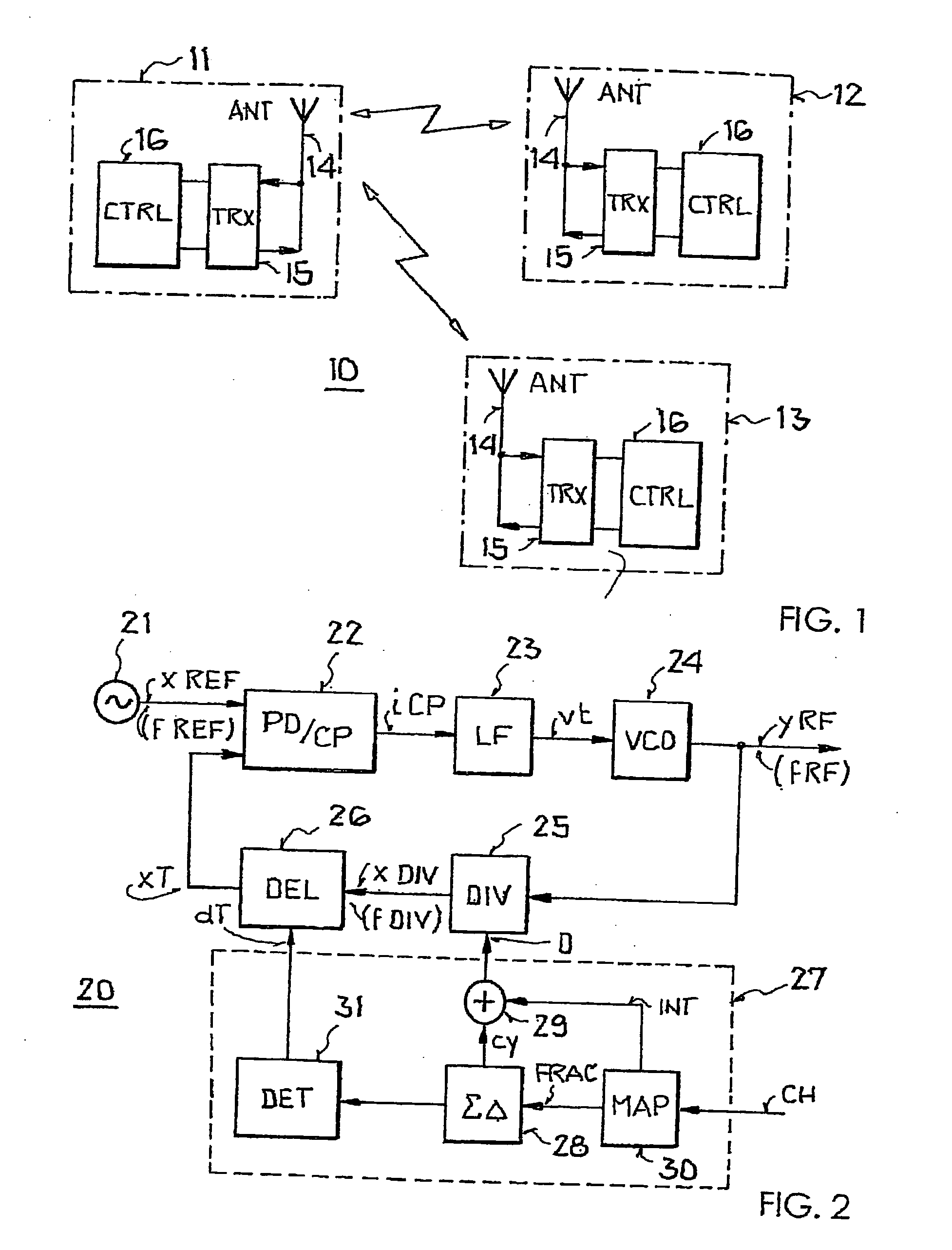
[0034] So-called “Wireless Personal Area Networks” (WPANS) may be used for the wireless transmission of information over relatively short distances. FIG. 1 shows an example of a WPAN 10 according to the standard IEEE 802.15.4. This standard specifies low-rate WPANs, which with raw data rates up to a maximum of 250 kbit / s and stationary or mobile devices are suitable for applications in industrial monitoring and control, in sensor networks, in automation, and in the field of computer peripherals and for interactive games. In addition to a very simple and cost-effective implementability of the devices, an extremely low power requirement of the device is of critical importance for such applications. Thus, an objective of this standard is a battery life of several months to several years.

[0035] The WPAN, shown in FIG. 1, comprises...


PUM


Abstract

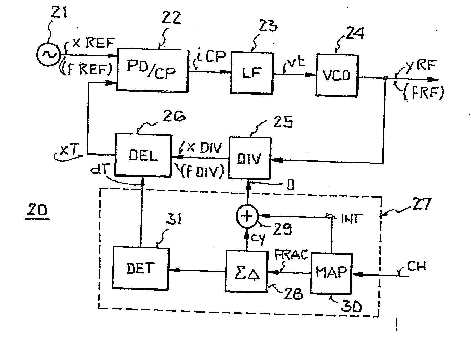
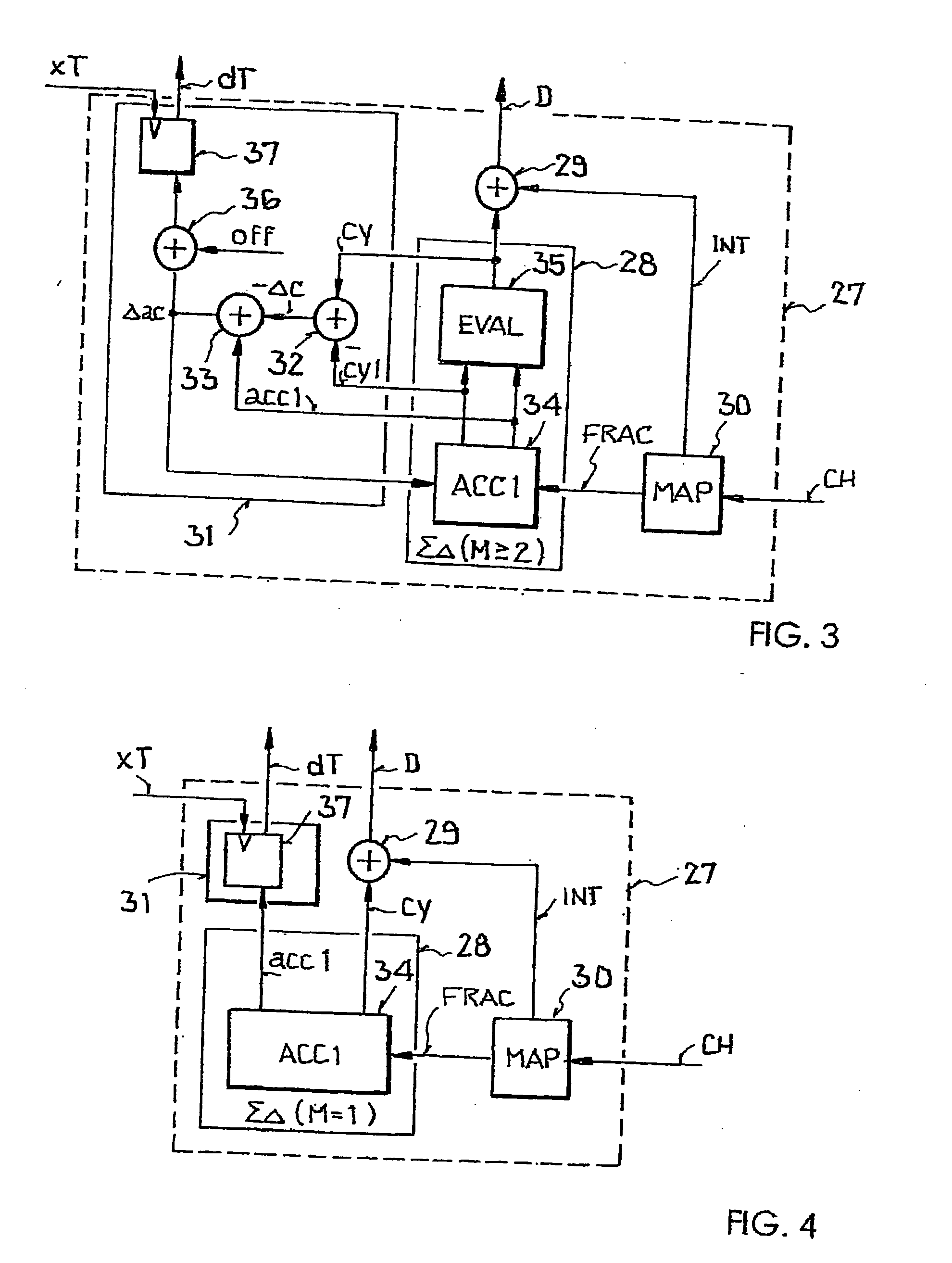
A PLL frequency generator is disclosed for generating an output signal with a settable target frequency, comprising a) a voltage-controlled oscillator for generating the output signal, b) a switchable frequency divider, which is connected to the voltage-controlled oscillator and is designed to derive from the output signal a frequency-divided signal whose instantaneous frequency depends on a value of an adjustable divisor, c) a switchable delay unit, which is connected to the frequency divider and is designed to generate a delayed signal in that the frequency-divided signal is delayed by delay times that depend on a control word, and d) a controller connected to the switchable delay unit controller and designed to determine the control words. According to the invention, the controller has a sigma-delta modulator and is designed to determine the control words depending on at least one signal provided by the sigma-delta modulator.

Description

[0001] This nonprovisional application claims priority under 35 U.S.C. § 119(a) on German Patent Application No. DE 102005060472, which was filed in Germany on Dec. 17, 2005, and which is herein incorporated by reference. BACKGROUND OF THE INVENTION [0002] 1. Field of the Invention [0003] The present invention relates to a PLL frequency generator (phase-locked loop). The invention relates furthermore to a transmitting / receiving device and to an integrated circuit with a PLL frequency generator of this type. [0004] 2. Description of the Background Art [0005] The invention falls within the field of telecommunications. It falls particularly within the field of PLL frequency generators, with whose help transmitting / receiving devices in telecommunication systems access spectrally spaced carrier frequency channels. Such PLL frequency generators derive an output signal with a settable target frequency from a highly precise reference signal and provide it as a local oscillator signal for re...

Claims


Application Information

Patent Timeline
Patent Type & Authority Applications(United States)
IPC IPC(8): H03L7/00
CPCH03L7/1976H03L7/081
Inventor BEYER, SASCHAJAEHNE, RALF
Owner ATMEL CORP
Learn More