Corona discharge ionizer

a technology of ionizer and corona, which is applied in the direction of corona discharge, electrostatic charge, emergency protective arrangement details, etc., can solve the problems of electrostatic breakage deterioration of the manufacturing yield of the electronic device, and practically difficult, and achieves noise reduction and simple structure.

Inactive Publication Date: 2007-07-12
HUGLE ELECTRONICS
View PDF3 Cites 16 Cited by
  • Summary
  • Abstract
  • Description
  • Claims
  • Application Information

AI Technical Summary

Benefits of technology

[0018] The present invention described above can make it possible to use a piezoelectric transformer by adding an effective ion balance function wit

Problems solved by technology

In a production process of electronic devices such as semiconductors (hereinafter, simply “electronic devices”), when static electricity is generated in the electronic device, there is caused a hazard that the electronic device is electrostatically broken by high voltage static electricity, or a hazard that micro particles floating in the air attach to a semiconductor circuit to cause a short circuit of the semiconductor circuit (hereinafter, simply “electrostatic hazard”).
Such hazards are serious factors which deteriorate manufacturing yield of the electr

Method used


Image

  • Corona discharge ionizer
  • Corona discharge ionizer
  • Corona discharge ionizer

Examples


Embodiment Construction

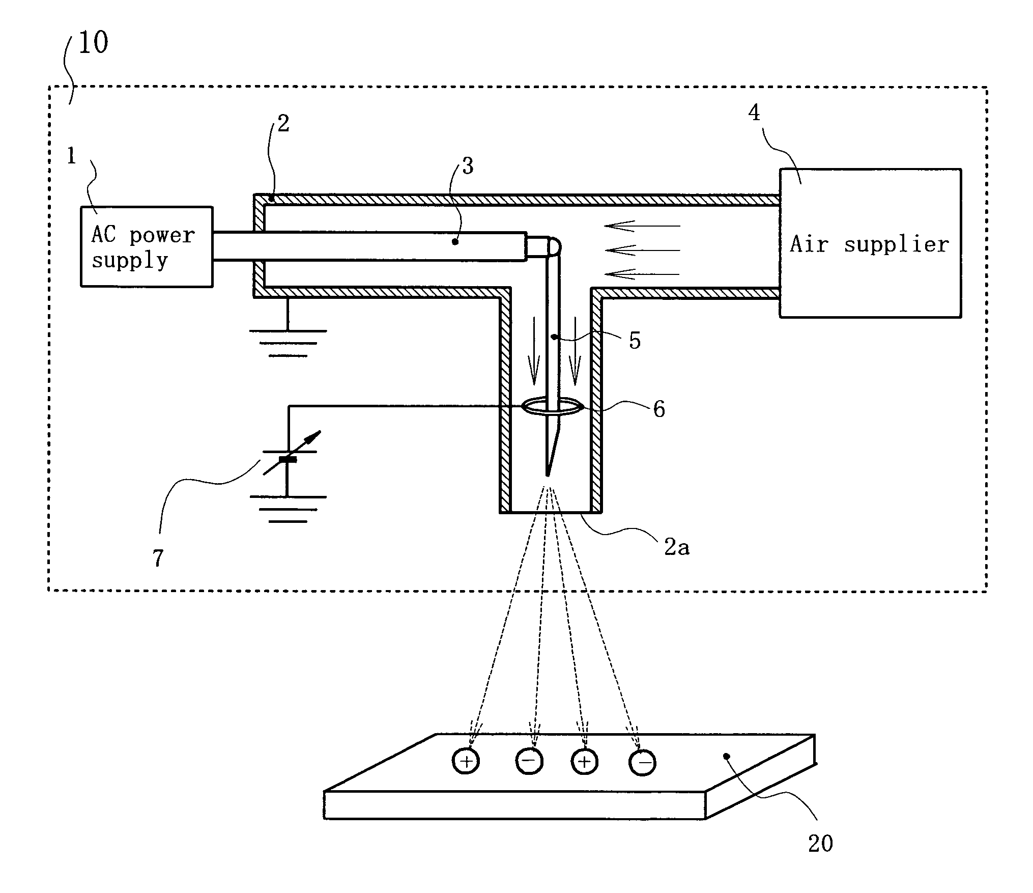
[0027] Best modes for carrying out the invention will be explained below based on the drawings. FIG. 1 is a block diagram of a corona discharge ionizer 10 according to an embodiment.

[0028] As shown in FIG. 1, the corona discharge ionizer 10 of the embodiment includes an AC power supply 1, an air supply pipe 2, a voltage supply line 3, an air supplier 4, an emitter 5, a control electrode 6, and a variable voltage supply unit 7. The corona discharge ionizer 10 sprays ions to a subject to be neutralized 20 to neutralize.

[0029] The AC power supply 1 is a voltage supply unit and applies high voltage to the emitter 5. The AC power supply 1 includes a piezoelectric transformer (not shown) to reduce noise.

[0030] The air supply pipe 2 injects compressed air supplied from the air supplier 4 under pressure from an air supply opening 2a. The air supply pipe 2 is formed such as to include a cylindrical portion covering around the emitter 5 (this cylindrical portion is a cylinder extending ver...


PUM


Abstract

To provide a corona discharge ionizer that makes it possible to use a piezoelectric transformer by adding an effective ion balance function with a simple structure without applying particular changes to the structure, and that realizes noise reduction.
In a corona discharge ionizer 10, a control electrode 6 is disposed in a cylindrical portion of an air supply pipe 2 which also functions as a shield body and at a location where ions are balanced. When a cylindrical inner diameter of the air supply pipe 2 is defined as Ds and an annular outer diameter of the control electrode 6 is defined as Dc, 2Dc<Ds is satisfied.

Description

TECHNICAL FIELD [0001] The present invention relates to a corona discharge ionizer having an ion balance control function. BACKGROUND ART [0002] In a production process of electronic devices such as semiconductors (hereinafter, simply “electronic devices”), when static electricity is generated in the electronic device, there is caused a hazard that the electronic device is electrostatically broken by high voltage static electricity, or a hazard that micro particles floating in the air attach to a semiconductor circuit to cause a short circuit of the semiconductor circuit (hereinafter, simply “electrostatic hazard”). Such hazards are serious factors which deteriorate manufacturing yield of the electronic devices. [0003] This problem can be solved if all of floating particles in a clean room can be removed, but this is practically difficult. Hence, attempt to solve the problem is made by neutralizing the static electricity of the electronic device. [0004] Conventionally, a corona disc...

Claims


Application Information

Patent Timeline
IPC IPC(8): H02H1/00H01T19/00H01T19/04H05F3/04
CPCH01T19/00H01T19/04H01T23/00H03F3/04
Inventor OKANO, KAZUO
Owner HUGLE ELECTRONICS
Why Eureka
Try Eureka