DC to DC converter

a dc converter and direct current technology, applied in the field of fly, can solve the problems of switching loss of the mosfet during the turn-on/turn-off state of the mosfet,

Inactive Publication Date: 2007-07-12
SAMSUNG ELECTRONICS CO LTD
View PDF4 Cites 37 Cited by
  • Summary
  • Abstract
  • Description
  • Claims
  • Application Information

AI Technical Summary

Benefits of technology

[0015] According to an aspect of the present invention, the second delay part comprises an inductor which is connected to a ground of the switching part and a second side of the capacitor and coupled with the primary winding and delays current flow in the switching part when the capacitor discharges a current when the switching part is turned-on.

Problems solved by technology

However, a switching loss occurs during a turn-on / turn-off state of the MOSFET because the related art flyback converter utilizes energy-conversion when devices such as the MOSFET are used for high-speed switching.
Accordingly, a large lead edge current occurs, resulting in switching loss of the MOSFET when the MOSFET is turned-on.

Method used


Image

  • DC to DC converter
  • DC to DC converter
  • DC to DC converter

Examples


Embodiment Construction

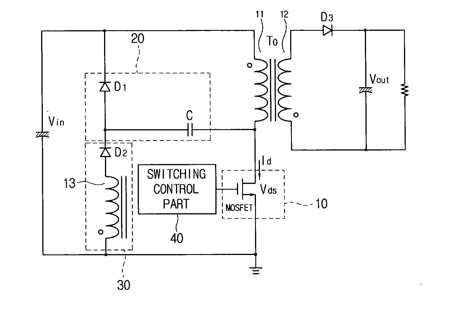
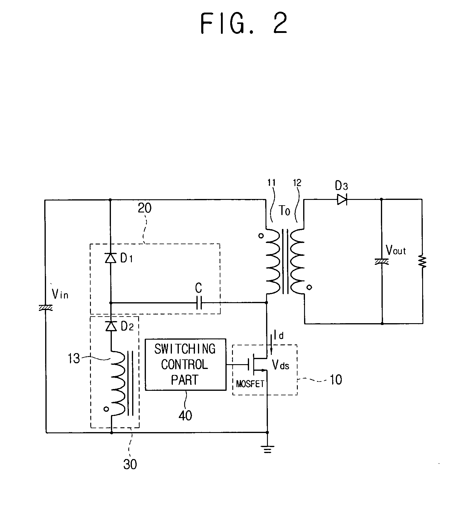
[0025] Reference will now be made in detail to the exemplary embodiments of the present invention, examples of which are illustrated in the accompanying drawings, wherein like reference numerals refer to like elements throughout. The exemplary embodiments are described below so as to explain the present invention by referring to the drawings. A flyback converter in which a quasi-resonant topology is applied will be described as an exemplary embodiment of the present invention.

[0026]FIG. 2 is a circuit diagram of a flyback converter according to an exemplary embodiment of the present invention. As shown in FIG. 2, the flyback converter, which converts an input DC voltage Vin into DC voltage of a predetermined level, may be divided into an input circuit having a primary winding 11 and an output circuit having a secondary winding 12.

[0027] The input circuit comprises the input voltage Vin supplying a DC voltage, the primary winding 11 of a transformer T0, a switching part 10, a first...


PUM


Abstract

A direct current (DC) to DC converter is provided. The DC to DC converter includes: a transformer which comprises a primary winding which is connected in series with an input voltage and a secondary winding which generates induced current when the input voltage is applied to the primary winding; a switching part which is connected to the primary winding and performs a switching operation according to a predetermined control signal; a first delay part which delays an increasing rate of voltage between open nodes according to a turned-off state of the switching part and supplies a discharge current when the switching part is turned-on; and a second delay part which delays current flow in the switching part when the first delay part discharges the current when the switching part is turned-on.

Description

CROSS-REFERENCE TO RELATED APPLICATIONS [0001] This application claims priority from Korean Patent Application No. 2006-0002748, filed on Jan. 10, 2006, in the Korean Intellectual Property Office, the disclosure of which is incorporated herein by reference in its entirety. BACKGROUND OF THE INVENTION [0002] 1. Field of the Invention [0003] Methods and apparatuses consistent with the present invention relate to a direct current (DC) to DC converter, and more particularly, to a flyback converter in which a quasi-resonant topology is applied. [0004] 2. Description of the Related Art [0005] A related art flyback converter such as a flyback converter with a quasi-resonant topology will be described with reference to FIG. 1. As shown in FIG. 1, the related art flyback converter comprises an input voltage Vin, a transformer T0 which has a primary winding 100 and a secondary winding 200, and a circuit device such as a metal oxide semiconductor field effect transistor (MOSFET) switch which i...

Claims


Application Information

Patent Timeline
Patent Type & Authority Applications(United States)
IPC IPC(8): H02M3/335
CPCH02M1/34Y02B70/1491H02M2001/346H02M3/335Y02B70/10H02M1/346H02M3/28
Inventor LEE, JIN-HYUNG
Owner SAMSUNG ELECTRONICS CO LTD
Why Eureka
Try Eureka