Brazing method and brazed structure

Inactive Publication Date: 2007-07-12
DENSO CORP
View PDF3 Cites 14 Cited by
  • Summary
  • Abstract
  • Description
  • Claims
  • Application Information

AI Technical Summary

Benefits of technology

[0006] The present invention was made in consideration of the above problems and has as its object to provide a novel brazing

Problems solved by technology

Due to these passive oxides, the wettability of the brazing material is poor.
Stainless steel is therefore known as a material difficult to braze.
Therefore, the copper fins soften due to the high temperature and strength is liable to be lost.
Further, there is also the technique of using a

Method used


Image

  • Brazing method and brazed structure
  • Brazing method and brazed structure
  • Brazing method and brazed structure

Examples


Embodiment Construction

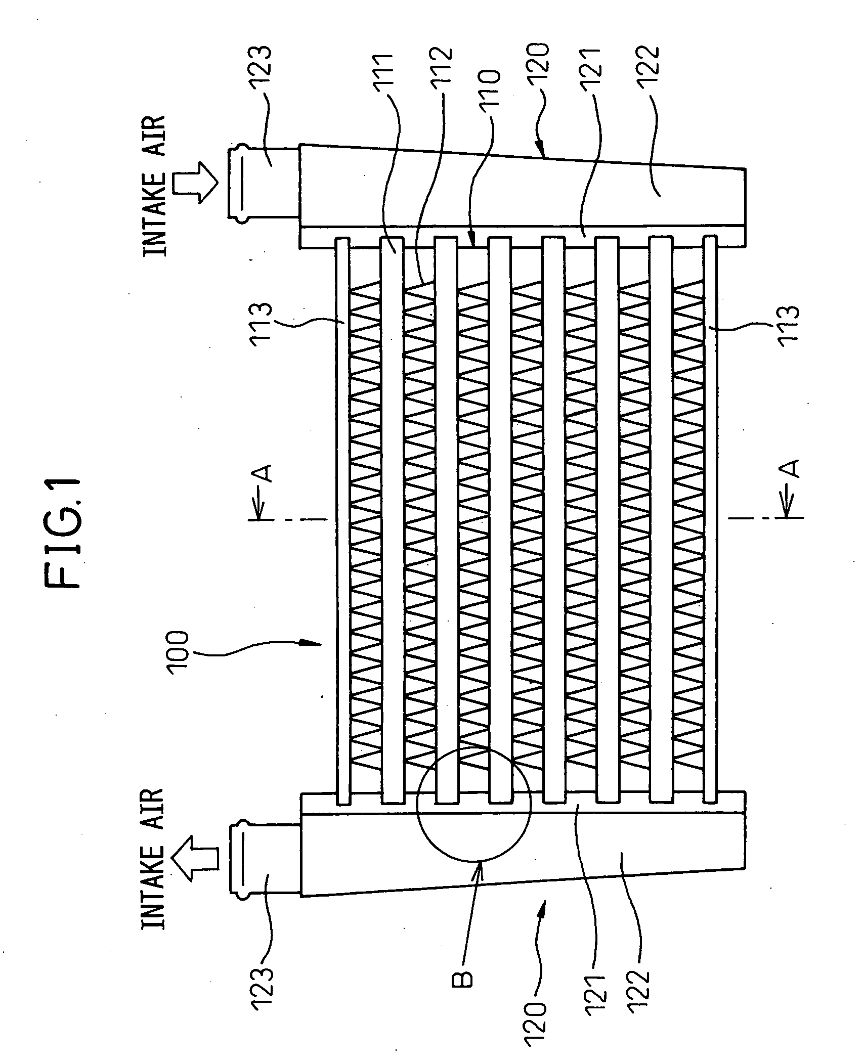
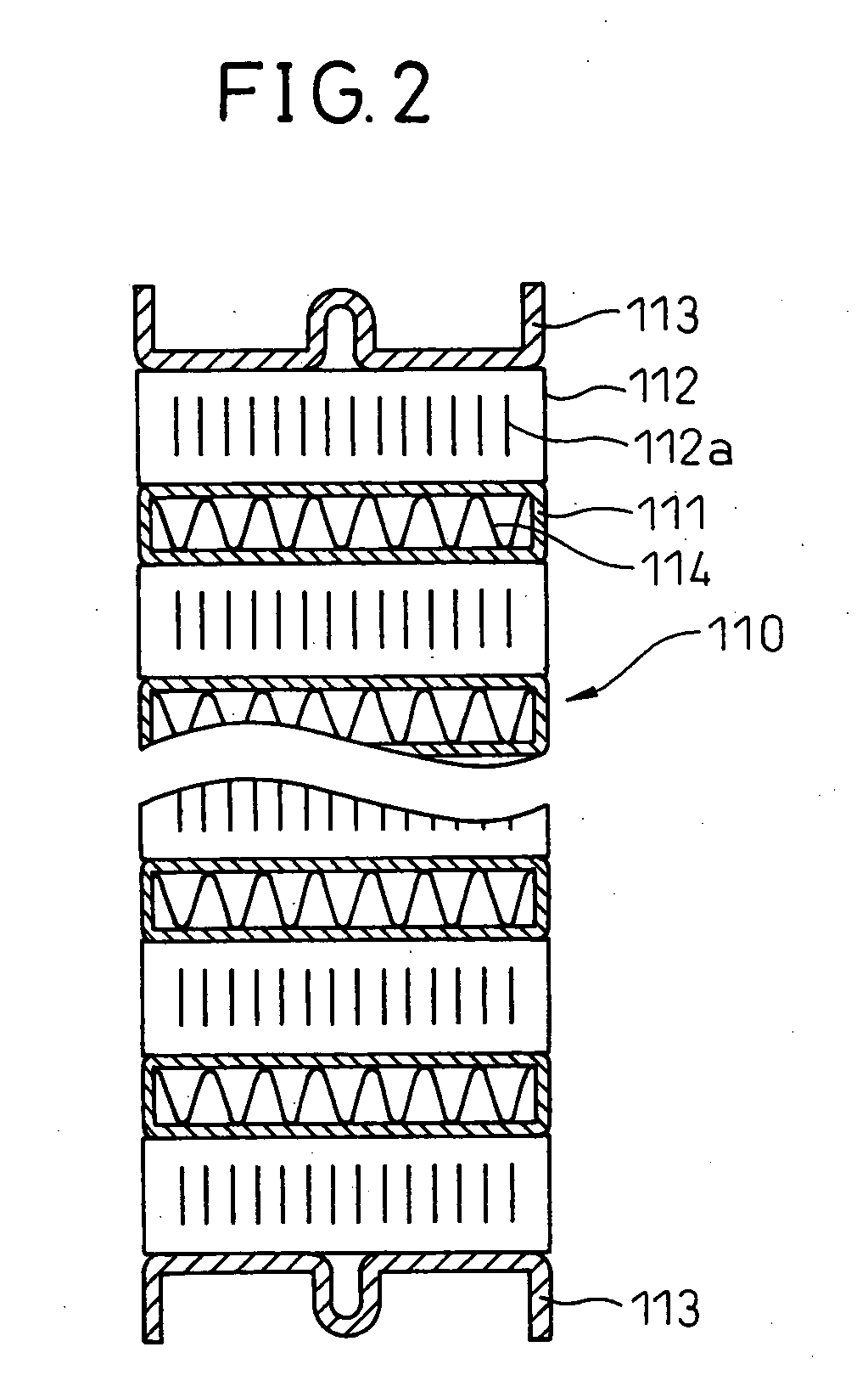
[0023] Below, embodiments of the present invention will be explained with reference to the drawings. FIG. 1 shows a heater exchanger, that is, an intercooler 100, to which the brazing method of the present invention is applied between a stainless steel header plate 121 and gold brass tubes 111, while FIG. 2 is a cross-section along A-A of FIG. 1.

[0024] The intercooler 100 cools the combustion use air sucked into a vehicular engine (internal combustion engine), that is, the intake, by heat exchange with cooling air from the outside. The intercooler 100 is comprised of a core part 110 and a pair of header tanks 120. The intercooler 100 shown as this embodiment is a large sized one mounted in a truck or other large sized vehicle. To obtain heat conductivity and durability, an iron-based material and copper-based material are used. The members are joined by brazing or welding. The brazing material used at the time of brazing is a low melting point four-way brazing material comprised of...


PUM

PropertyMeasurementUnit
Melting pointaaaaaaaaaa

Abstract

A method of brazing different types of metals by a low melting point brazing material is provided. First, a surface of a first metal member is covered by a material enabling brazing with a second metal member along with diffusion of a brazing material. Next, a low melting point brazing material is arranged at the covered surface. Further, the low melting point brazing material is made to melt.

Description

TECHNICAL FIELD [0001] The present invention relates to a method of brazing together different types of metals, more particularly relates to a brazing method enabling brazing using a low melting point brazing material. BACKGROUND ART [0002] In brazing together different types of metals, to obtain a good brazability or solderability, the wettability of the brazing material at the surface of the matrix material is important. However, for example, the surface of stainless steel has tough oxides called “passive oxides”. Due to these passive oxides, the wettability of the brazing material is poor. Stainless steel is therefore known as a material difficult to braze. [0003] In the past, various methods have been proposed for brazing together different types of metals. For example, it is known to plate the outer surface of stainless steel tubes with copper and braze copper fin plates to the copper (see Japanese Patent Publication (A) No. 7-80633). However, the copper plating parts melt to b...

Claims


Application Information

Patent Timeline
IPC IPC(8): B32B15/20B32B15/18
CPCB23K1/0012B23K2201/14B23K2203/02B23K2203/12C25D7/00Y10T428/12764F28F1/128F28F9/0224F28F9/18F28F21/089Y10T428/1291F28D1/05366B23K2101/14B23K2103/02B23K2103/12
Inventor WATANABE, HARUHIKOSUSA, SUMIOHARADA, MASAKI
Owner DENSO CORP
Why Eureka
Try Eureka