
Minimally invasive spinal fusion

a spinal fusion, minimally invasive technology, applied in the direction of internal osteosynthesis, medical science, internal osteosynthesis, etc., to achieve the effect of good material strength, easy deformation, and easy bending

Active Publication Date: 2007-07-12
MAZOR ROBOTICS
View PDF54 Cites 104 Cited by
  • Summary
  • Abstract
  • Description
  • Claims
  • Application Information

AI Technical Summary

Benefits of technology

[0009] The present invention seeks to provide a new method and apparatus by which spinal fusion can be performed in a manner less invasive than possible using the above-described prior art methods. According to the present invention, use is made of vertebral connecting rods made of a material which changes its rigidity as a function of temperature, with the change taking place in a temperature region just below that of body temperature. One such group of materials is known as Shape Memory Alloys (hereinafter abbreviated to SMA), whose crystalline structure undergoes a phase change from austenitic to martensitic when cooled through the range of temperatures over which the phase transformation occurs, and vice versa as the material is heated up over the transition temperature range. In the austenitic phase, SMA's have rigid properties, with good material strength. In the martensitic phase, SMA's are readily deformable, the level of flexibility depending on the particular SMA used. While in the martensitic phase, such SMA materials can be readily bent into shapes very different from their original shape. In addition, such materials show shape memory, in that, regardless of the shape into which the material is bent below its transition point, it will return not only to its original rigidity when its temperature rises above the transition temperature, but also to the original shape into which it was annealed before being cooled. The phase change from martensitic to austenitic phase (and vice versa) can be selected to be somewhat below body temperature, or even below room temperature, depending on the particular SMA composition chosen.
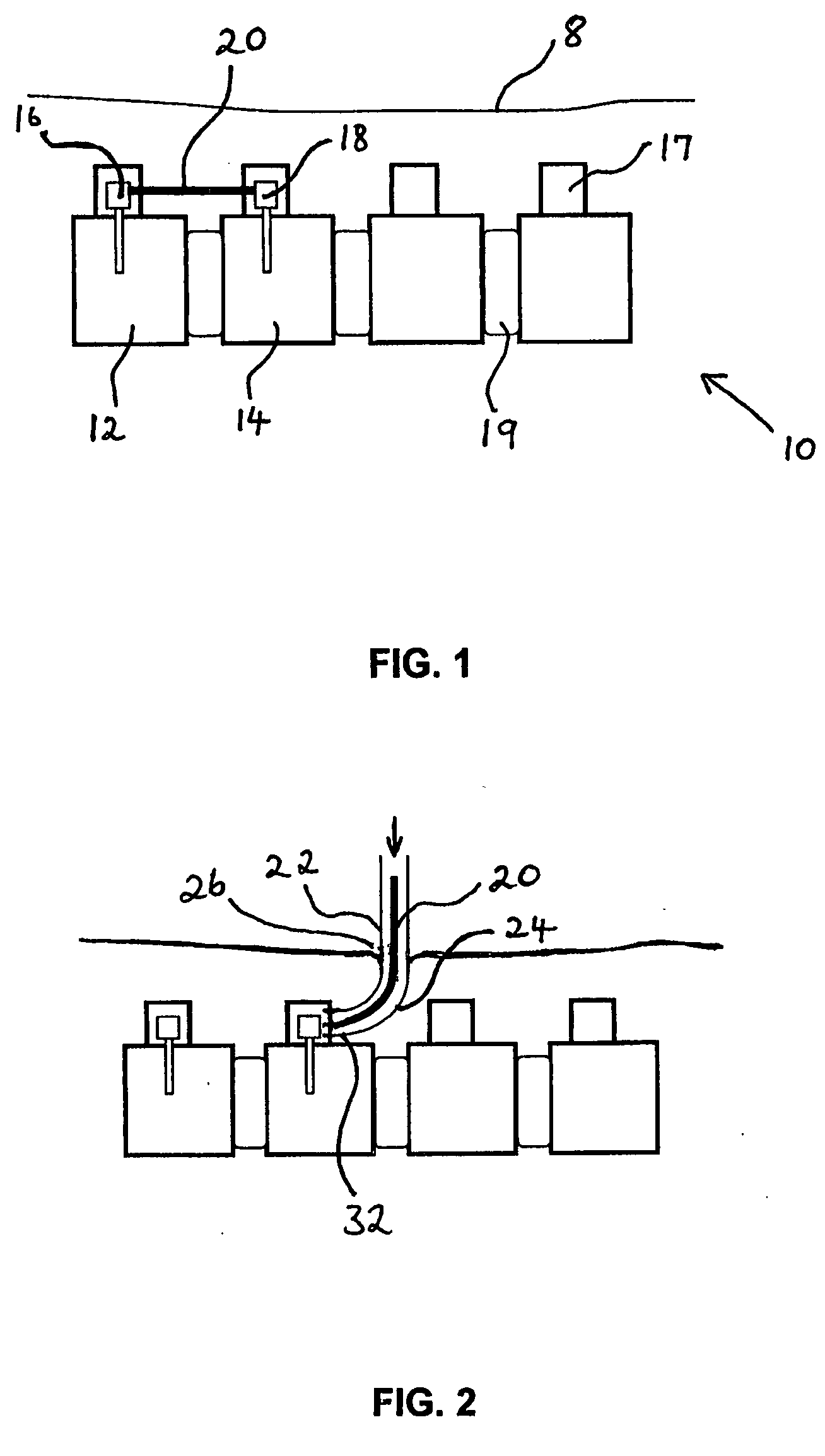
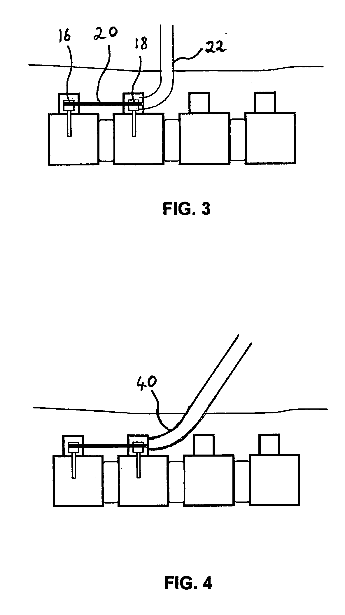
[0010] In order to use the vertebral fusion system of the present invention, pedicle screws are first inserted into the relevant vertebrae, in a minimally invasive manner. Then, in accordance with a preferred embodiment of the present invention, a curved tube is inserted into an incision in the patient's back, until its inserted end is located close to one of the pedicle screw heads to which the connecting rod is to be attached. The tube can be inserted through an opening no larger than the diameter of the tube, such that the incision can be small. A connecting rod made of an SMA material, and cooled to below its transition point, is inserted down the tube, and, because of its flexibility below its transition point, readily negotiates the curved end of the tube, to exit the tube in a direction essentially parallel to the spine. Once it has exited the delivery tube, the SMA rod heats up by contact with the body tissue around it, switches phase to its rigid state, and at the same time, regains its original straight form as a result of the shape memory effect. Once in this state, it can be pushed through the tissue and muscle between the vertebrae after exiting the end of the tube, until it reaches its final intended position between the pedicle screw heads. It is then attached to the pedicle screw heads preferably in the conventional manner using set screws, and the insertion tube is then withdrawn. The delivery tube is preferably left in position until after the connecting rod has been firmly attached to the pedicle screws, in order to provide additional support to the rod during the tightening procedure.
[0012] In using the vertebral fusion system of the present invention, only small incisions are required either side of each vertebra for inserting the pedicle screws. According to one preferred embodiment, the curved delivery tube can be inserted through this same incision, and maneuvered into its correct position by stretching the tissue around the incision hole to get to the correct position for delivery of the connecting rod. According to another preferred embodiment, an additional small incision is made near each pedicle screw insertion incision, and the delivery tube inserted through this additional hole. Thus, according to either of these embodiments, the invasiveness of the procedure is substantially reduced, even compared to the above-mentioned minimally invasive methods.
[0040] There is further provided in accordance with yet another preferred embodiment of the present invention, an insert for implanting in the body of a subject, the insert comprising a shape memory material, and wherein the insert has a final shape after insertion in the body essentially the same as its shape before insertion. The shape memory material is preferably such that the flexibility of the insert is increased during insertion, such that the insert changes its shape during insertion.
[0045] (iv) allowing the insert to regain its predefined shape within the body of the subject. Furthermore, according to this method, the change of temperature of the insert is preferably such that the rigidity of the insert decreases, the decreased rigidity enabling the predefined shape to change during insertion.

Problems solved by technology

However, these prior art applications generally involve a device having one defined shape outside the body when cooled, and when heated by the body after insertion, they regain their original pre-cooling shape, which is different from the cooled shape before insertion.

Method used


Image

  • Minimally invasive spinal fusion
  • Minimally invasive spinal fusion
  • Minimally invasive spinal fusion

Examples


Embodiment Construction

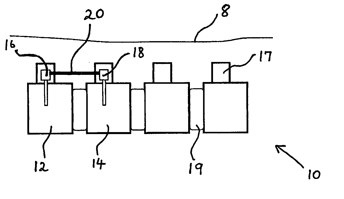
[0055] Reference is now made to FIG. 1, which illustrates schematically a sectional side view of a number of vertebrae of a spine 10 situated beneath the skin 8 of a subject, with an adjacent pair of vertebrae 12, 14, fused together using two pedicle screws 16, 18 and a connecting rod 20. The spinous process 17 of each vertebra, the vertebrae themselves, and the disc 19 are shown schematically in FIG. 1. It is to be understood that there is an additional connecting rod between pedicle screws inserted into the other lateral side of the spine, and unseen in the side view of FIG. 1.

[0056] Reference is now made to FIG. 2 which schematically illustrates an SMA rod 20, according to a preferred embodiment of the present invention, constructed and operative as a vertebral connecting rod. The rod is shown being inserted through a curved insertion tube 22, while being held at a temperature below its transition point. At such a temperature, the rod is sufficiently flexible to pass round the c...


PUM


Abstract

A system and method for performing spinal fusion using vertebral connecting rods constructed of a shape memory material, such as shape memory alloy. The connecting rod is cooled below its phase transition temperature, which is chosen to be just below body temperature, and is inserted through a curved guide tube previously inserted into the back of the patient. The guide tube is located so as to deliver the connecting rod at its desired location between the preinserted pedicle screw heads. The rod, being in its flexible state below the transition temperature, negotiates the curve and exits the guide tube in a straight form and parallel to the patient's spine. As it heats up to body temperature, it regains its original straight shape and its original rigidity, and is ready for connecting its associated vertebrae to each other.

Description

FIELD OF THE INVENTION [0001] The present invention relates to the field of spinal fusion using connecting rods, and especially to connecting rods that can be inserted by minimally invasive procedures. BACKGROUND OF THE INVENTION [0002] Vertebral fusion is a common spinal surgical procedure, performed in order to overcome problems related to impaired mutual interaction between neighboring vertebrae. The technique involves the disablement of the relative mechanical motion between adjacent vertebrae, the stimulating of growth of inter-vertebra hard tissue, causing the two vertebrae to fuse and thus preventing compression during body movements and stabilizing the spinal column. Spinal fusion is a very common procedure, with an estimated over 400,000 procedures performed annually in the USA alone. [0003] A common method for fusing two vertebrae is by means of connecting rods, one on either side of the spine, each rod connecting two pedicle screws inserted into the pedicles of the two ad...

Claims


Application Information

Patent Timeline
IPC IPC(8): A61F2/30
CPCA61B17/7002A61B2017/00867A61B17/7089A61B17/7083
Inventor SHOHAM, MOSHE
Owner MAZOR ROBOTICS
Learn More