Flow transform for integrated circuit design and simulation having combined data flow, control flow, and memory flow views

Inactive Publication Date: 2007-07-12
KOTA BHASKAR
View PDF36 Cites 8 Cited by
  • Summary
  • Abstract
  • Description
  • Claims
  • Application Information

AI Technical Summary

Benefits of technology

[0036] In exemplary embodiments, the method may also include (d1) generating from the functional simulation a second selection of a plurality of computational elements and corresponding control code for an implementation of the algorithm; (e1) functionally simulating the algorithm using a plurality of cycle-accurate computational element models corresponding to the second selection and the corresponding control code; and (f1) comparing the functional simulations using the first selection and the second selection.
[0037] In another exemplary embodiment, a machine-readable medium storing instructions for electronic system level design and verification comprises: a first program construct for receiving an application as design input and receiving a plurality of architecture definition files, the plurality of architecture definition files having been determined from control and memory-based integrated circuit modeling; a second program construct for performing a first functional simulation of the application to provide a functional application model; a third program construct for verifying the functional application model; a fourth program construct for providing the verified functional application model in a hardware simulation compatible format; a

Problems solved by technology

These EDA tool suites, however, have been unable to integrate this level of verification with system level designs and requirements, for testing and verifying algorithmic performance and power and control specifications, for example.
In addition, prior art EDA and ESL design and simulation tool suites have generally been inapplicable to data flow processing architectures or data streaming architectures, which are designed to execute whenever input data exists and provide corresponding output data.
Such data flow architectures have typically been difficult to design and model because typical data flow models, while accounting for data input and output, have insufficient control information for execution control and further fail to account for memory requirements, movements and flows.
In addition, such prior art data flow models do not provide sufficient interface information or provide incompatible interfaces, so that one dataflow element can

Method used


Image

  • Flow transform for integrated circuit design and simulation having combined data flow, control flow, and memory flow views
  • Flow transform for integrated circuit design and simulation having combined data flow, control flow, and memory flow views
  • Flow transform for integrated circuit design and simulation having combined data flow, control flow, and memory flow views

Examples


embodiment 500

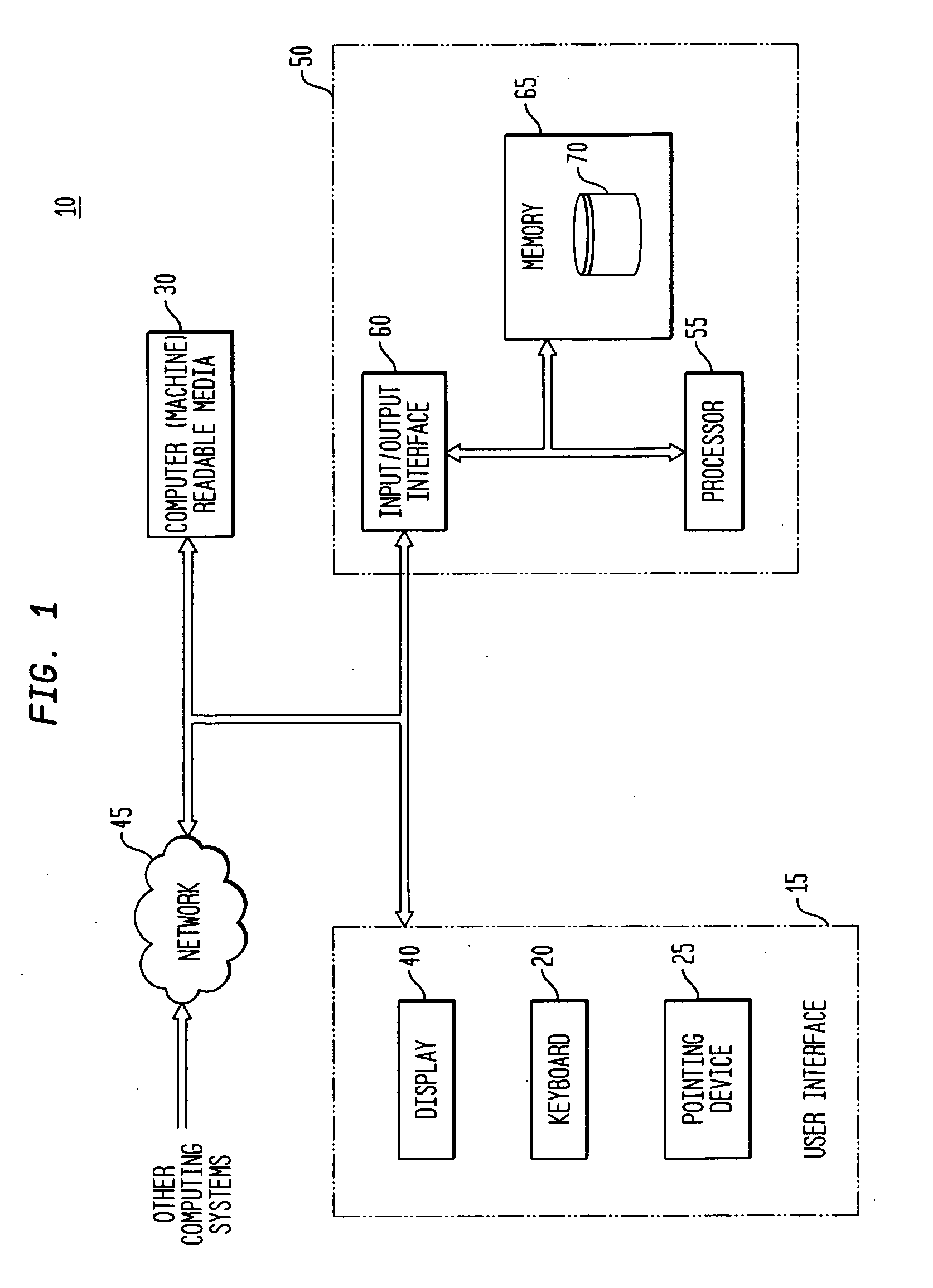
[0074]FIG. 6 is a block and flow diagram illustrating an exemplary Algorithmic ESL design, simulation and modeling automation platform system embodiment 500, referred to herein as an “Algorithmic ESL system”500, in accordance with the teachings of the present invention. The Algorithmic ESL system 500 illustrated in FIG. 6 provides an infrastructure to (1) architect an IC, such as an adaptive computing IC or “system-on-a-chip” (“SoC”); (2) generate applications to run on the architecture; (3) functionally simulate algorithms and applications; (4) simulate and model the architecture with given applications; (5) simulate and model the applications as operating on the target architecture; and (6) compile the application to the target architecture (illustrated in FIG. 7). The Algorithmic ESL system 500 (and 600, below) is embodied as one or more systems 10 and / or apparatuses 50 illustrated and discussed with reference to FIG. 1.

[0075] The Algorithmic ESL system 500 may generally be divid...

embodiment 600

[0093]FIG. 7 is a block and flow diagram providing another, more high-level illustration of an exemplary Algorithmic ESL design, simulation and modeling automation platform system embodiment 600 in accordance with the teachings of the present invention, and further illustrates the integration of the AESL platform with other significant components, such as compiler 650. In FIG. 7, the various outputs from the various platforms are illustrated as databases, namely, a functional models database 605 (provided by the application and system design platform 520 for use in interactive and iterative functional simulation and modeling), a computational element (or other device) models database 615 (provided by the instruction (or control) and memory-based modeling platform 510, in conjunction with the system modeling and simulation platform 540), and a cycle-accurate models database 610 (provided by the application and system design platform 520 in conjunction with the information from the co...


PUM


Abstract

The exemplary embodiments of the invention provide a method, system and software for developing and simulating an integrated circuit architecture. An exemplary method includes inputting an algorithm using an instruction language having control information; decomposing the algorithm to a plurality of tasks; for each task of the plurality of tasks, determining and combining data flow, control flow, and memory flow to form a flow transform of a corresponding plurality of flow transforms; connecting the plurality of flow transforms using a FIFO memory interconnect between each flow transform to provide an algorithm representation; and simulating the connected flow transforms. The method may be repeated at different levels of abstractions and utilizing different types and mixes of computational elements implementing the flow transforms. Hardware description and models of the computational elements may also be generated, including corresponding control bits for control of computational elements selected to implement a corresponding flow transform.

Description

CROSS-REFERENCE TO A RELATED APPLICATION [0001] This application is related to and claims priority to U.S. patent application Ser. No. ______, filed concurrently herewith, inventors Bhaskar Kota, Paul L. Master, Robert William Barker, and Robert Plunkett, entitled “Algorithmic Electronic System Level Design Platform”, which is commonly assigned herewith, the contents of which are incorporated herein by reference, and with priority claimed for all commonly disclosed subject matter.FIELD OF THE INVENTION [0002] The present invention relates, in general, to electronic design automation and electronic system level design automation for integrated circuits and applications and, more particularly, to a method, system and software for creating a flow transform having combined data flow, control flow, and memory flow, for use in design and simulation of integrated circuitry. BACKGROUND OF THE INVENTION [0003] Electronic Design Automation (“EDA”) and Electronic System Level (“ESL”) design an...

Claims


Application Information

Patent Timeline
IPC IPC(8): G06F15/00
CPCG06F17/5022G06F30/33
Inventor KOTA, BHASKAR
Owner KOTA BHASKAR
Why Eureka
Try Eureka