
Method and apparatus for posttreatment of an exhaust gas from an internal combustion engine

a posttreatment and exhaust gas technology, applied in mechanical equipment, machines/engines, transportation and packaging, etc., can solve the problems of affecting the flow of exhaust gas, affecting the unproblematic, and the wall temperature of the exhaust gas line cannot always be above the boiling temperature of the higher-molecular ingredients of the commercial fuel used

Inactive Publication Date: 2007-07-19
ROBERT BOSCH GMBH
View PDF9 Cites 73 Cited by
  • Summary
  • Abstract
  • Description
  • Claims
  • Application Information

AI Technical Summary

Benefits of technology

The invention relates to a method and apparatus for post-treating exhaust gas from internal combustion engines. The technical effects of the invention include reducing deposits in the exhaust gas line, improving the conversion rates of urea in SCR processes, and accelerating the heating up of fuel for regenerating catalytic converters or burning off diesel particle filters. The invention also includes a low thermal capacity impact plate that heats up quickly to the temperature of the exhaust gas, and a turbulent exhaust gas flow to improve mixing with the substance sprayed into the exhaust gas.

Problems solved by technology

In both cases, particularly at low exhaust gas speeds, it cannot be avoided that some of the urea-water solution will meet the wall of the exhaust gas line, which particularly at low exhaust gas or wall temperatures leads to the development of deposits of urea or urea reaction products.
In these deposits, urea or urea reaction products are stored, and at a later point they can be undesirably released again, and particularly in a transient mode of operation of the engine, they can be a hindrance to an unproblematic, optimized denitrification process.
Moreover, the deposits can increase the flow resistance of the exhaust gas line and thus impair the exhaust gas flow.
However, since the exhaust gas line is more or less severely cooled, among other factors by the relative wind of the motor vehicle, it cannot always be assured that the wall temperature of the exhaust gas line will be above the boiling temperatures of the higher-molecular ingredients of the commercial fuels used.

Method used


Image

  • Method and apparatus for posttreatment of an exhaust gas from an internal combustion engine
  • Method and apparatus for posttreatment of an exhaust gas from an internal combustion engine
  • Method and apparatus for posttreatment of an exhaust gas from an internal combustion engine

Examples


Embodiment Construction

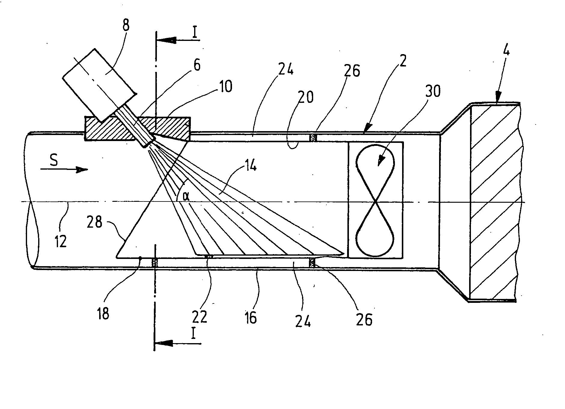
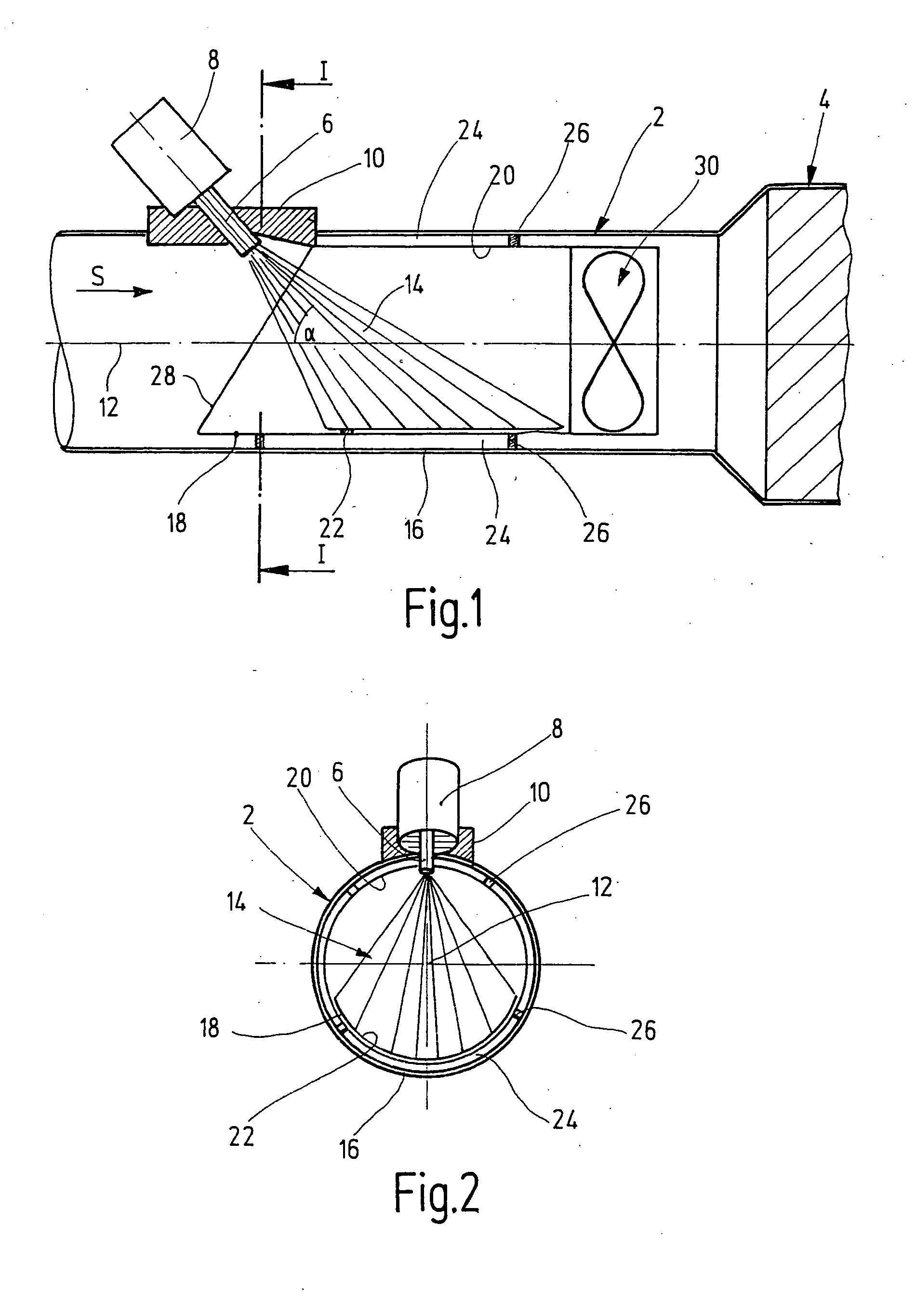
[0020]FIG. 1 shows a short portion of an exhaust manifold or tail pipe 2 of a motor vehicle with a diesel engine, between the engine (not shown) and a catalytic converter 4, which is also partly shown on the right-hand side of FIG. 1, and in which nitrogen oxides NOx contained in the tail pipe exhaust gas are reduced by reacting with ammonia NH3, forming nitrogen N2 and water H2O.

[0021] For generating the ammonia that is needed for reducing the nitrogen oxides in the catalytic converter 4, a urea-water solution is sprayed, upstream in terms of the flow direction from a catalytic converter 4 in a manner known per se, through a spray nozzle 6 of a cooled injection valve or metering valve 8 into the exhaust gas flowing through the tail pipe 2. The spray nozzle 6 is retained by an adapter 10, which is inserted into the cylindrical wall of the tail pipe 2, and the nozzle is inclined to the longitudinal axis 12 of the tail pipe 2 so that a convergent spray stream or mist 14 emerging from...


PUM

PropertyMeasurementUnit
exhaust gas temperaturesaaaaaaaaaa
thermal capacityaaaaaaaaaa
thermal conductivityaaaaaaaaaa

Abstract

A method of and an apparatus for posttreatment of an exhaust gas from an internal combustion engine, in which a substance to be mixed with the exhaust gas is sprayed in metered quantities into an exhaust gas line through which the exhaust gas flows. The substance is sprayed onto an impact plate disposed inside the exhaust gas line.

Description

[0001] The invention relates to a method and an apparatus for posttreatment of an exhaust gas from an internal combustion engine, having the characteristics recited in the preambles to claims 1 and 4, respectively. PRIOR ART [0002] Apparatuses of the type defined at the outset, with which a substance to be mixed with the exhaust gas from an internal combustion engine is sprayed in metered quantities into an exhaust gas line through which exhaust gas flows are known for two different purposes. [0003] First, a urea-water solution (UWS) is sprayed into the exhaust gas from diesel engines, to reduce the proportion of nitrogen oxides NOx in the exhaust gas. The urea in the sprayed-in solution is converted here in the exhaust gas line itself, or in a hydrolysis catalytic converter optionally located in the exhaust gas line, into ammonia NH3, which in a downstream SCR catalytic converter reduces the nitrogen oxides NOx, forming nitrogen N2 and water H2O. The delivery of the urea-water solu...

Claims


Application Information

Patent Timeline
Patent Type & Authority Applications(United States)
IPC IPC(8): F01N3/00F01N3/10B01F3/04B01F5/04F01N3/025F01N3/08F01N3/20F01N3/28F01N3/36
CPCB01F3/04049F01N3/2066F01N3/2892F01N3/36F01N13/16F01N2240/20B01F5/0473F01N2610/02F01N2610/102F01N2610/1453Y02T10/24B01F5/0268F01N2470/24Y02T10/12B01F23/2132B01F25/25B01F25/3141F01N3/08F01N3/20F01N3/025F01N3/00
Inventor MEINGAST, ULRICHDEHN, JOHANNESEGGERT, TORSTEN
Owner ROBERT BOSCH GMBH
Learn More