
Process for producing microparticles and apparatus therefor

Inactive Publication Date: 2007-07-19
MITSUI MINING & SMELTING CO LTD
View PDF0 Cites 67 Cited by
  • Summary
  • Abstract
  • Description
  • Claims
  • Application Information

AI Technical Summary

Benefits of technology

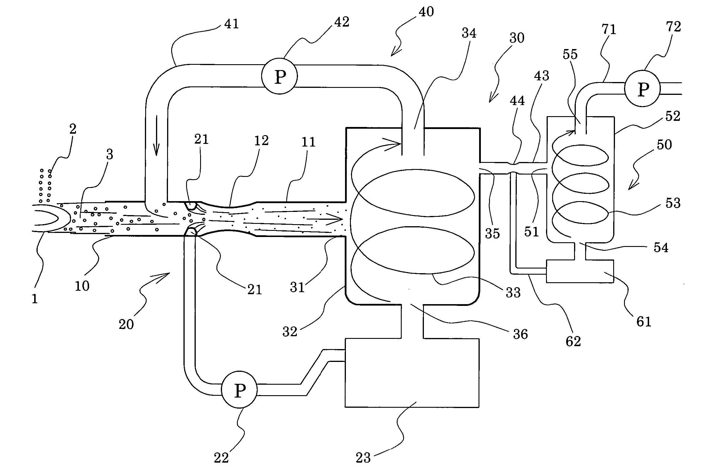
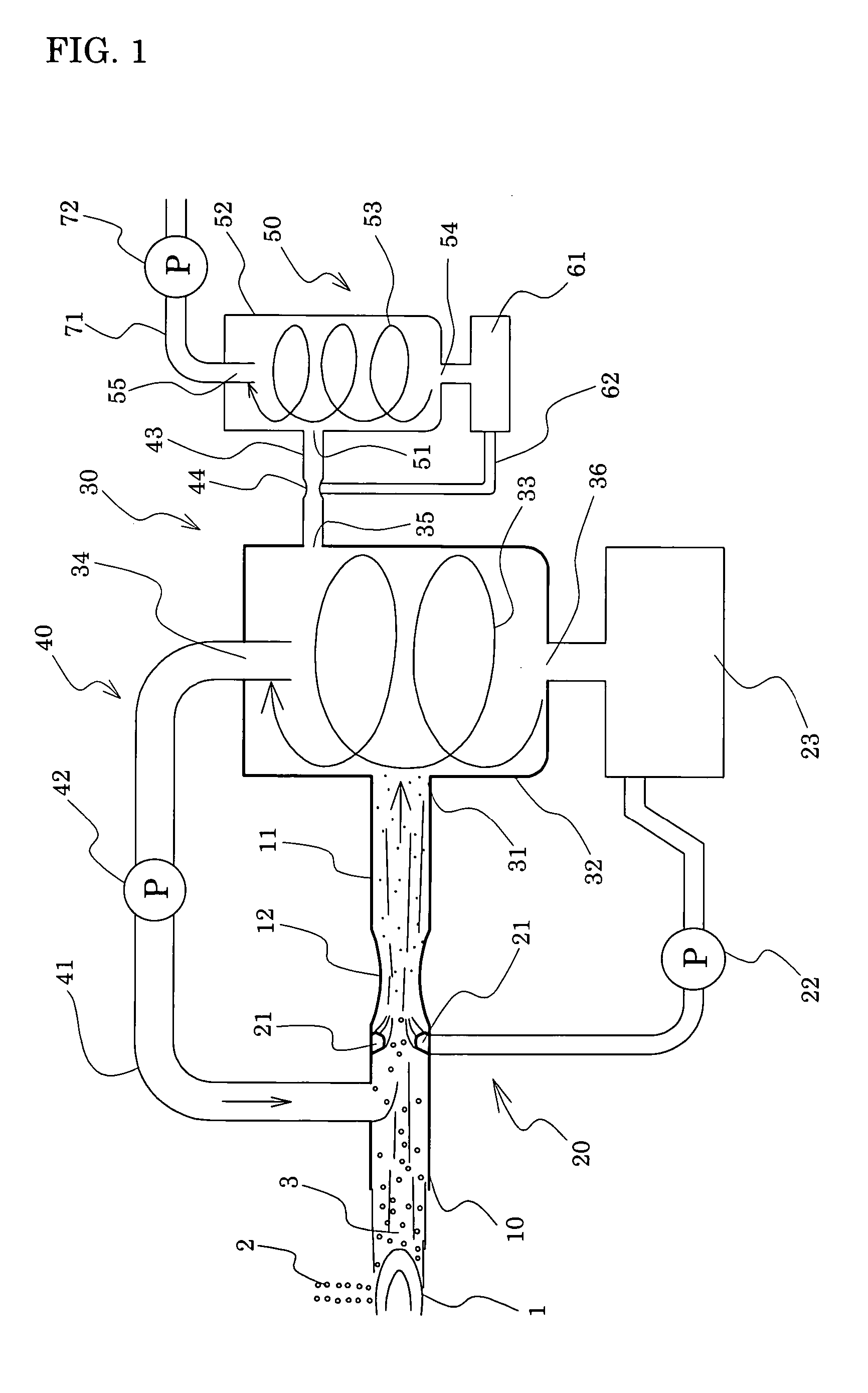
[0066] As described hereinabove, according to the present invention, a raw material metal or alloy in the form of a liquid stream, liquid droplets, or powder is fed into a heat source, and the formed product in the form of microparticles is captured by means of an atomized liquid fluid. Thus, microparticles can be effectively produced in a simple manner.

Problems solved by technology

However, use of a high-speed gas flow at a Mach number of >1 requires large facilities, problematically impeding production of ITO powder at low cost and with high efficiency.
However, the above dry-synthesis methods may be unsuitable for producing ITO powder.
Thus, currently, dry-synthesis of ITO powder is not carried out on an industrial scale.

Method used


Image

  • Process for producing microparticles and apparatus therefor
  • Process for producing microparticles and apparatus therefor
  • Process for producing microparticles and apparatus therefor

Examples


example 1

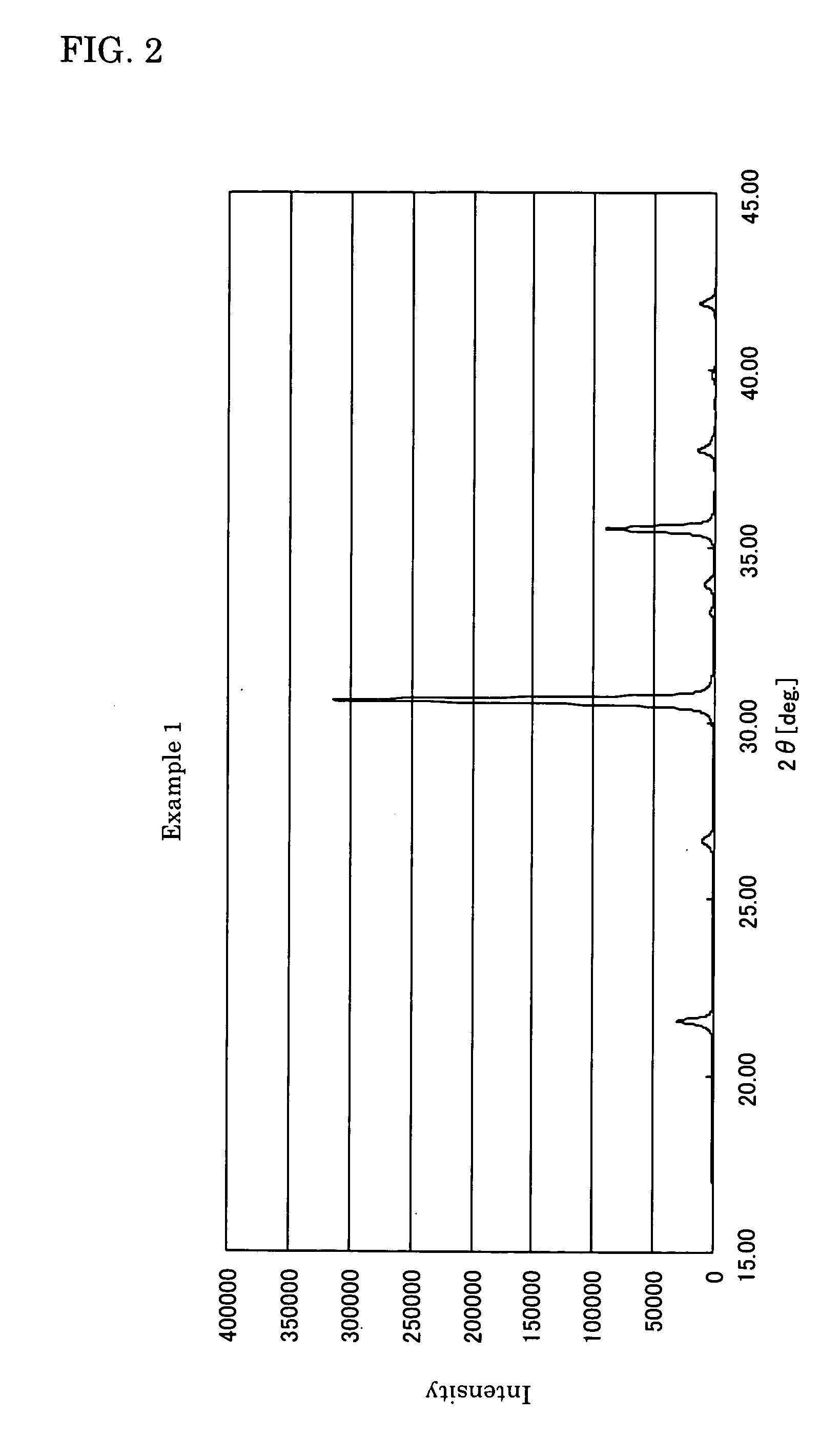
[0098] An atomized powder (mean particle size: 45 μm) of In—Sn alloy (Sn: 9.6 wt. %) was introduced to acetylene flame, to thereby synthesize an ITO (In2O3:SnO2=90:10 wt. %) powder under dry conditions. The powder was collected by means of a bag filter under dry conditions, to thereby yield an ITO powder of Example 1.

example 2

[0099] In a manner similar to that of Example 1, an ITO powder was synthesized by means of acetylene flame under dry conditions. The powder was collected by jetting water to the powder under wet conditions, to thereby yield an ITO powder of Example 2.

example 3

[0109] An atomized powder (mean particle size: 45 μm) of In—Sn alloy (Sn: 9.6 wt. %) was introduced to DC plasma flame, to thereby synthesize an ITO (In2O3:SnO2=90:10 wt. %) powder under dry conditions. The powder was collected by jetting water to the powder under wet conditions, to thereby yield an ITO powder of Example 3.


PUM

PropertyMeasurementUnit
Percent by massaaaaaaaaaa
Speedaaaaaaaaaa
Heataaaaaaaaaa

Abstract

The invention provides a process for producing microparticles, which process enables production of microparticles such as oxide microparticles by means of a simple apparatus at low cost and which is suitable for producing ITO powder, and an apparatus for producing the microparticles. In the process for producing microparticles, a raw material in the form of a liquid stream, liquid droplets, or powder is fed into a heat source; the formed product in the form of microparticles is captured by means of an atomized liquid fluid; and the microparticles in the form of slurry are collected through gas-liquid separation.

Description

TECHNICAL FIELD [0001] The present invention relates to a process for producing microparticles of a material such as indium oxide-tin oxide powder, and to an apparatus for producing the microparticles. BACKGROUND ART [0002] Sputtering is a generally known technique for forming thin film. In the sputtering technique, a thin film is formed by sputtering a sputtering target. The sputtering technique is employed in industrial processes, since a thin film of large surface area can be readily formed, and a high-performance film can be formed at high efficiency. In recent years, various sputtering techniques have been known, such as reactive sputtering; i.e., sputtering in a reactive gas, and magnetron sputtering, which realizes high-speed thin film formation by placing a magnet on the backside of a target. [0003] Among thin film products obtained through sputtering, indium oxide-tin oxide (In2O3—SnO2 compound oxide, hereinafter abbreviated to as ITO) film is a transparent conductive film ...

Claims


Application Information

Patent Timeline
IPC IPC(8): C22B5/20C22C1/04C21B15/04B22F1/00B22F9/00B01J19/00B01J19/24C01B13/32C01B13/34C01B21/06C01B21/082C01G1/02C01G19/00
CPCB01J8/0055B01J19/088C01P2002/72C01G19/00C01G1/02B01J2219/00108B01J2219/00112B01J2219/00114B01J2219/00123B01J2219/00159B01J2219/0877B01J2219/0879B01J2219/0894B22F9/026B22F9/082B22F2998/00C01B13/322C01B13/326C01B13/34C01B21/06C01B21/0821B22F2202/13B01J2/02B01J19/24
Inventor TAKAHASHI, SEIICHIROWATANABE, HIROSHI
Owner MITSUI MINING & SMELTING CO LTD
Learn More