
Thermal insulating material and pollution control device using the same

Inactive Publication Date: 2009-04-28
3M INNOVATIVE PROPERTIES CO
View PDF23 Cites 1 Cited by
  • Summary
  • Abstract
  • Description
  • Claims
  • Application Information

AI Technical Summary

Benefits of technology

[0010]It is, therefore, an object of the present invention to provide a thermal insulating material which can be efficiently produced while the content of organic matters such as organic fibers and / or an organic binder is reduced to the same or lower degree as compared with the thermal insulating material used in a conventional pollution control device (e.g., catalytic converter), and which can be applied to a pollution control element (e.g., catalytic element) while avoiding, as much as possible, an unpleasant feeling to the operator.

Problems solved by technology

However, the thermal insulating material as disclosed in the above publications (Kokai) can not be easily used, together with a high sensitivity oxygen sensor.
That is, since an organic matter such as organic fibers and / or organic binder are added in the above thermal insulating material in a comparatively large amount, i.e. about 4 to 50% wt %, based on the total amount of the thermal insulating material, the organic matter is likely to be easily incorporated into the exhaust gas on initial operation of the catalytic converter, thereby to cause wrong operation of the exhaust gas purification system.
However, since the surface of this thermal insulating material is covered with a protective sheet, an additional complicated step of removing the protective sheet must be carried out after the thermal insulating material was disposed between a casing and a catalyst support so as to apply it to a catalytic converter.
There is also a problem about disposal of the removed protective sheet.
However, a complicated step of laminating a plurality of mats must be required because of a multi-layer structure of the thermal insulating material.
The holding seal material is likely to cause protrusion or scattering of inorganic fibers from the surface of the insulating material, although the organic matter is removed by calcining the laminated material.
As a result, the end portion of the inorganic fibers tends to be directly contacted with the operator to impart an unpleasant feeling to him on incorporation of the above holding seal material into the catalyst converter.

Method used


Image

  • Thermal insulating material and pollution control device using the same
  • Thermal insulating material and pollution control device using the same
  • Thermal insulating material and pollution control device using the same

Examples


example 1

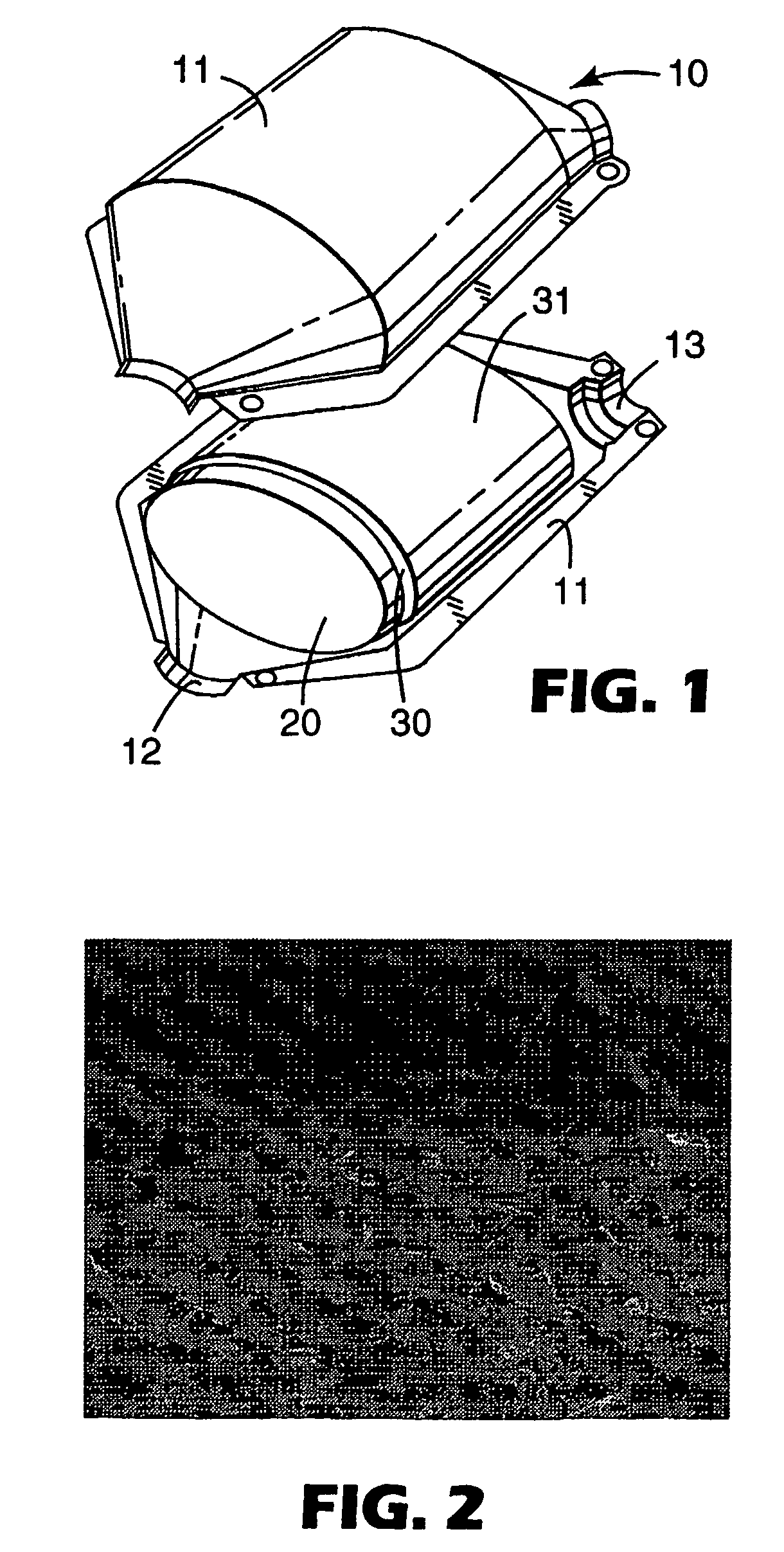
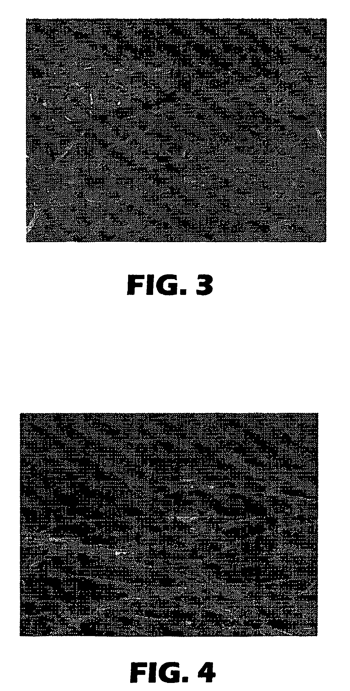
[0078]First, a coating material of polyacrylic acid (manufactured by NIPPON ZEON Co., Ltd. under the trade name of “LX-816”, solid content of 42%) was diluted with water at a dilution degree of 5 time to prepare a coating solution. Both surfaces of a thermal insulating material body (manufactured by MITSUBISHI CHEMICALS Co., Ltd. under the trade name of “MAFTEC BLANKET”) composed mainly of a laminated material of inorganic fibers of crystalline alumina were spray coated with the coating solution. The coating weight of the coating solution was controlled so that the weight of the organic matter containing the coating material is 1% or less based on the total weight. The coating solution was dried to obtain a thermal insulating material.

example 2

[0079]In the same manner as in Example 1, except that both surfaces of the thermal insulating material body were coated with about 0.3 g of a coating solution (manufactured by ODEC Co. under the trade name of “SERACOAT 22-T”) of an aqueous potassium phosphate solution by spraying and then dried, a thermal insulating material was made.

example 3

[0080]In the same manner as in Example 2, except that both surfaces of the thermal insulating material body were coated with about 0.3 g of an aqueous potassium silicate solution and dried, and then further coated with about 0.3 g of a coating solution (manufactured by ODEC Co. under the trade name of “MASTER SEAL”) of an aqueous aluminum phosphate solution by spraying, and then dried, a thermal insulating material was made.


PUM

PropertyMeasurementUnit
Temperatureaaaaaaaaaa

Abstract

A thermal insulating material which can be efficiently produced while the content of organic matters, such as organic fibers and / or an organic binder, is reduced to the same or lower degree as compared with the thermal insulating material used in a conventional pollution control device (e.g., catalytic converter), and which can be applied to a pollution control element (e.g., catalytic element) while avoiding, as much as possible, an unpleasant feeling to the operator. A thermal insulating material comprising a thermal insulating material body formed of a bulk material of inorganic fibers, and a coating provided on at least one surface of said thermal insulating material body.

Description

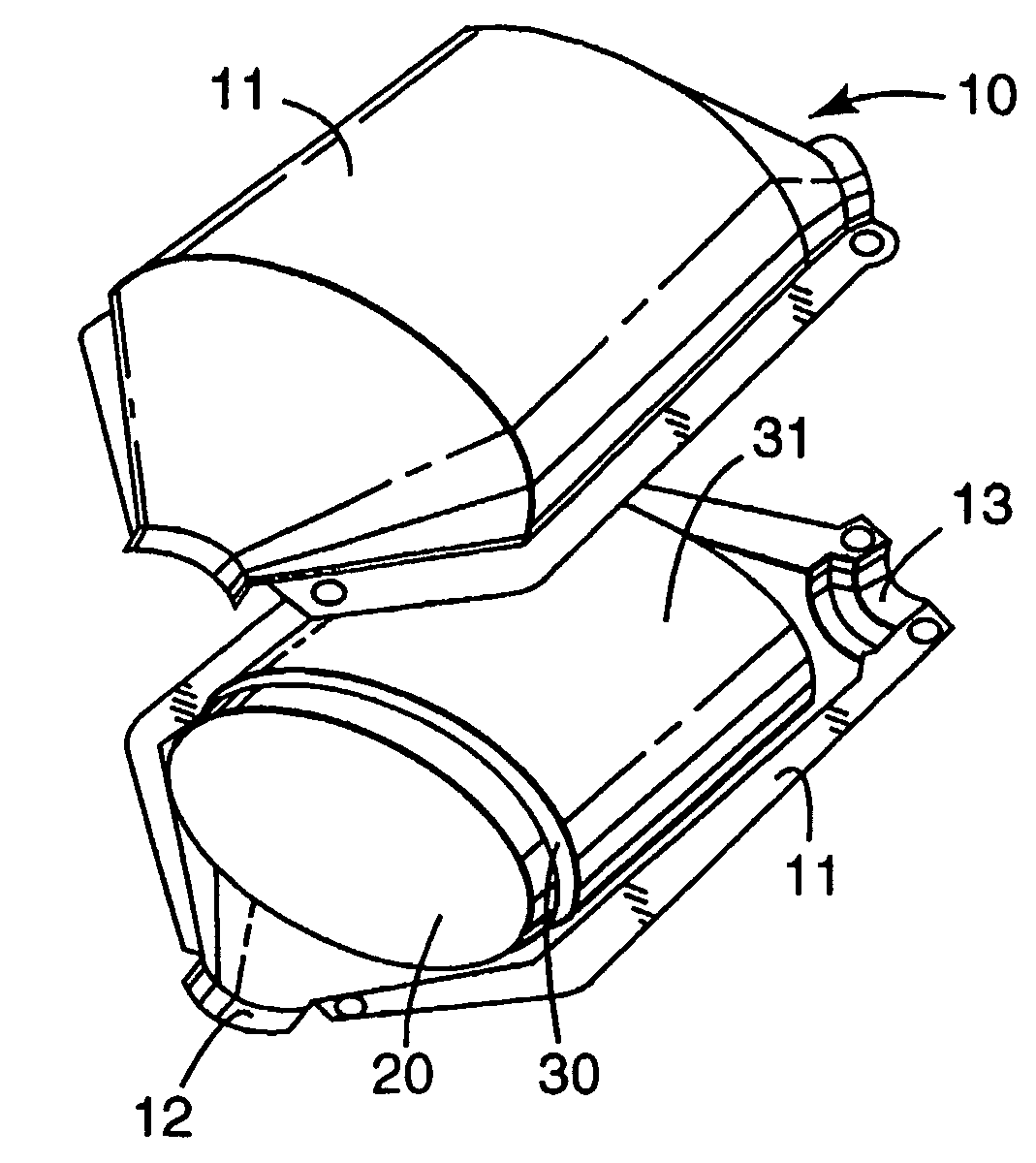
FIELD OF THE INVENTION[0001]The present invention relates to a thermal insulating material, particularly, a thermal insulating material for use in a pollution control device and, more particularly, a pollution control device wherein a thermal insulating material is used to retain a pollution control element in a casing.BACKGROUND OF THE INVENTION[0002]Exhaust gas purifying systems using a pollution control device to purify the exhaust gas of an internal combustion engine, are well known. Pollution control devices include catalytic converters and exhaust gas filters (e.g., diesel particulate filters). For example, it is well known to use ceramic catalytic converters to purify an exhaust gas containing carbon monoxide (CO) and hydrocarbon (HC) exhausted from the engine of automobiles. In general, a pollution control device includes a pollution control element mounted in a housing. For example, a ceramic catalytic converter basically contains a honeycomb catalyst support (catalyst elem...

Claims


Application Information

Patent Timeline
IPC IPC(8): B32B21/00A47G19/22B29D22/00B32B23/08B32B23/00B28B21/72B29D23/00B32B1/08C04B30/02F01N3/28F16L59/00
CPCC04B30/02F01N3/2853F16L59/00C04B14/4625C04B41/483C04B14/042C04B14/42C04B40/0028C04B41/5089C04B41/5015Y10S55/30C04B2111/28C04B2111/00793Y10T428/2978Y10T428/1314Y10T442/2926Y10T442/2975Y10T442/674Y10T442/696Y10T442/697Y10T442/699
Inventor AIZAWA, TAKUMAKASAI, TOSHIHIROKAWAI, TAKAYUKIWATANABE, TOSHIYUKI
Owner 3M INNOVATIVE PROPERTIES CO
Learn More