
Method for producing particles and apparatus for producing particles

Active Publication Date: 2015-09-24
RICOH KK
View PDF1 Cites 1 Cited by
  • Summary
  • Abstract
  • Description
  • Claims
  • Application Information

AI Technical Summary

Benefits of technology

The present invention provides a method for producing particles that can efficiently produce particles with a narrow particle size distribution. This solves various problems in the art.

Problems solved by technology

In the case where fluids each having different viscosities, such as a melt resin and liquid carbon oxide, are mixed using a static mixer like in the case of PTL 1, however, it is difficult to homogeneously mix the both fluids together.
As a result, the both fluids may not be homogeneously mixed.
Therefore, the compressive fluid is not sufficiently dissolved in the thermoplastic resin, so that a viscosity of the thermoplastic resin is not sufficiently reduced.
Accordingly, there is a problem that it is difficult to produce a large amount of uniform particles having small particle diameters.
However, these countermeasures are not effective method for preventing the compressive fluid, which is a low viscous fluid, from passing through, and therefore there are problems, such as an increase in pressure loss during mixing, an enlarged device, and an increase in washing effort.

Method used


Image

  • Method for producing particles and apparatus for producing particles
  • Method for producing particles and apparatus for producing particles
  • Method for producing particles and apparatus for producing particles

Examples


synthesis example 1

Synthesis of Polyester Resin 1 (Pressure Plastic Material)

[0126]A reaction vessel equipped with a cooling tube, a stirrer, and a nitrogen inlet tube was charged with 229 parts of a bisphenol A ethylene oxide (2 mol) adduct, 529 parts of a bisphenol A propylene oxide (3 mol) adduct, 208 parts, of terephthalic acid, 46 parts of adipic acid, and 2 parts of dibutyl tin oxide, and the mixture was allowed to react for 8 hours at 230° C. under the atmospheric pressure. The resultant was further allowed to react for 5 hours under the reduced pressure of 10 mmHg to 15 mmHg. Thereafter, 44 parts of trimellitic anhydride was added to the reaction vessel, and the resulting mixture was allowed to react for 2 hours at 180° C. under the atmospheric pressure to thereby yield Polyester Resin 1.

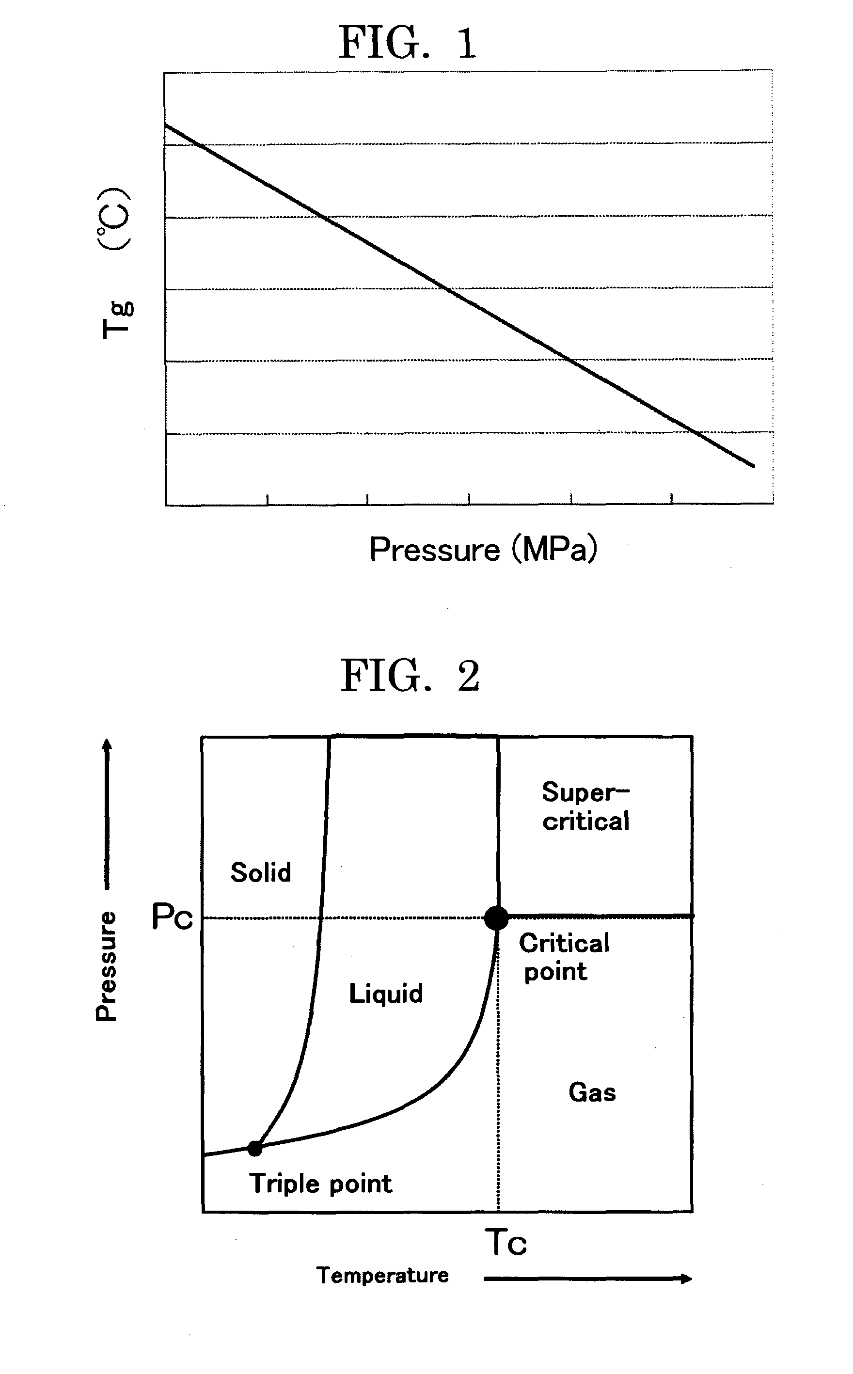
[0127]Polyester Resin 1 had the number average molecular weight of 2,500, weight average molecular weight of 6,700, glass transition temperature (Tg) of 43° C., and acid value of 25 mgKOH / g. The gradient of th...

example 1

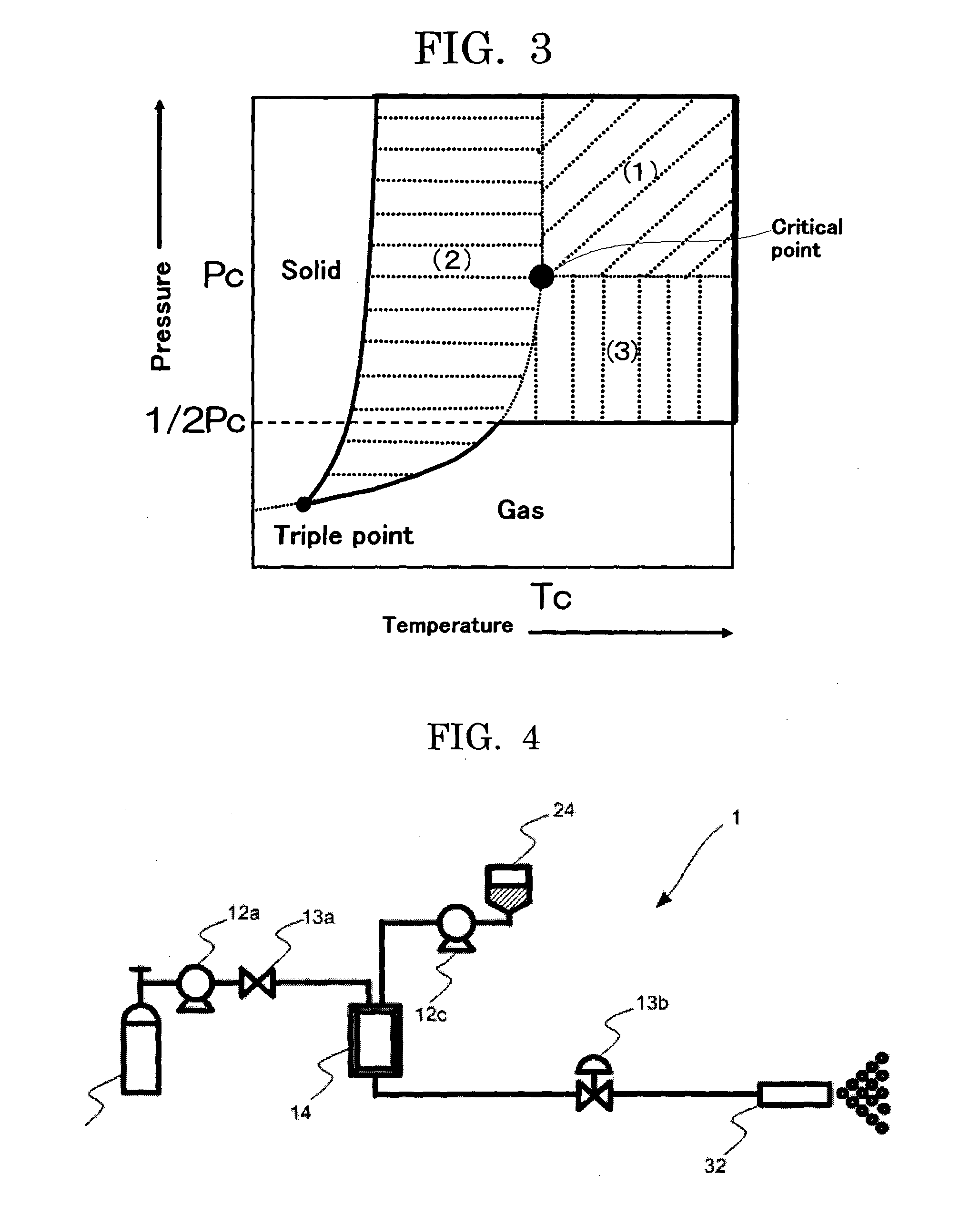
[0129]Color particles were produced by means of an apparatus for producing particles, 1, illustrated in FIG. 4. In Example 1, a compressive fluid was obtained by heating and compressing carbon dioxide stored in the bomb 11.

[0130]

Polyester Resin 195 parts by massColorant (copper phthalocyanine blue, C.I. Pigment 5 parts by massBlue 15:3, manufactured by Dainichiseika Color andChemicals Mfg. Co., Ltd.)

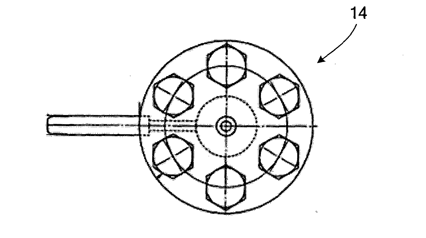
[0131]After mixing the raw materials of color particles by a mixer, the mixture was melt-kneaded by a two-roll mill, and the kneaded product was rolled and cooled. This melt-kneaded product was provided to a pressure tank equipped with a thermoregulator 24 of the apparatus for producing particles 1 illustrated in FIG. 4, and was heated and melted at 120° C. The melt-kneaded product, which had been heated and melted, was supplied into the multistage split flow micromixer 14 illustrated in FIGS. 6A to 6D by pressurizing by a pump 12c, and at the same time, carbon dioxide as a supercritical...


PUM

PropertyMeasurementUnit
Viscosityaaaaaaaaaa
Dynamic viscosityaaaaaaaaaa
Pressureaaaaaaaaaa

Abstract

To provide a method for producing particles, which contains: bringing a compressive fluid and a pressure plastic material into contact with each other using a multistage split flow micromixer, to thereby produce a melt of the pressure plastic material, in which the compressive fluid is dissolved; and jetting the melt of the pressure plastic material, to form particles, wherein the pressure plastic material is a resin having a carbonyl structure —C(═O)—, and wherein a viscosity of the melt is 500 mPa·s or lower, as measured under temperature and pressure conditions at the time of the jetting the melt of the pressure plastic material.

Description

TECHNICAL FIELD[0001]The present invention relates to a method for producing particles and an apparatus for producing particles.BACKGROUND ART[0002]Recently, proposed has been a method for producing a toner, which include melting a thermoplastic resin and bringing the melt resin into contact with a compressive fluid, followed by mixing the melt resin and the compressive fluid by a conventional type of a static mixer, to reduce a viscosity of the melt resin, and decompress the obtained mixture to expand, to thereby produce a toner (see PTL 1). According to this proposed method, a toner can be produced with maintaining energy cost low.[0003]In the case where fluids each having different viscosities, such as a melt resin and liquid carbon oxide, are mixed using a static mixer like in the case of PTL 1, however, it is difficult to homogeneously mix the both fluids together. As for the static mixer, known is a static mixer having a mixing element in a tube-shaped housing. The mixing elem...

Claims


Application Information

Patent Timeline
IPC IPC(8): C08K5/3417B01J2/04B01F23/47
CPCB01J2/04C08K5/3417B29B7/32B29B9/10G03G9/081B01F25/4521B01F33/3011
Inventor OSAKA, KEIKOTANAKA, CHIAKISUZUKI, AKIRAKAWASAKI, SHINICHIRO
Owner RICOH KK
Learn More