Electric machine signal selecting element

a signal selection and electric machine technology, applied in piezoelectric/electrostrictive devices, piezoelectric/electrostrictive/magnetostrictive devices, electrical apparatus, etc., can solve the problems of low signal selection efficiency, low cost, and difficult miniaturization of selection devices using electric resonance in lc or the like often used in wireless communication. , to achieve the effect of low cost, low cost and simple structur

Inactive Publication Date: 2007-07-19
PANASONIC CORP
View PDF6 Cites 141 Cited by
  • Summary
  • Abstract
  • Description
  • Claims
  • Application Information

AI Technical Summary

Benefits of technology

[0055] As described above, according to the present invention, a change in physical property caused by a structural change of a micro-vibrator generated when the micro-vibrator vibrates with its self-resonant frequency is used as a mechanism for signal selection. Accordingly, only a signal with a predetermined frequency can be selectively output.
[0056] Since it is not necessary to provide any sensitive vibration sensing mechanism, an electromechanical signal selection device with a high frequency signal selection function, which can manufactured with a simple structure and at a low cost is produced.
[0057] A mechanism for giving an external force to the micro-vibrator to thereby excite vibration therein is also dispensable. Further, the structure becomes simple. Thus, the electromechanical signal selection device can be manufactured at a low cost.
[0058] The electromechanical signal selection device according to the present invention is applicable not only to an electric circuit for wireless communication but also to electric circuits for various applications.
[0059] The electromechanical signal selection device according to the present invention can be also used as a resonator. Therefore, the electromechanical signal selection device can be used in an oscillator, and in a block of an electric circuit such as a mixer or an amplifier.

Problems solved by technology

Particularly signal selection devices using electric resonance in LC or the like often used in wireless communications are difficult to miniaturize because the size of resonators depends on the electric length.
As the micro-vibrator becomes finer from a micrometer order to a nanometer order, vibration thereof becomes extremely slight and close to a noise level of quantum vibration or thermal vibration.

Method used


Image

  • Electric machine signal selecting element
  • Electric machine signal selecting element
  • Electric machine signal selecting element

Examples


embodiment 1

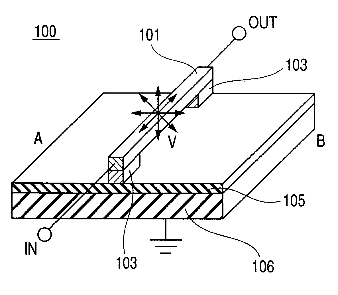
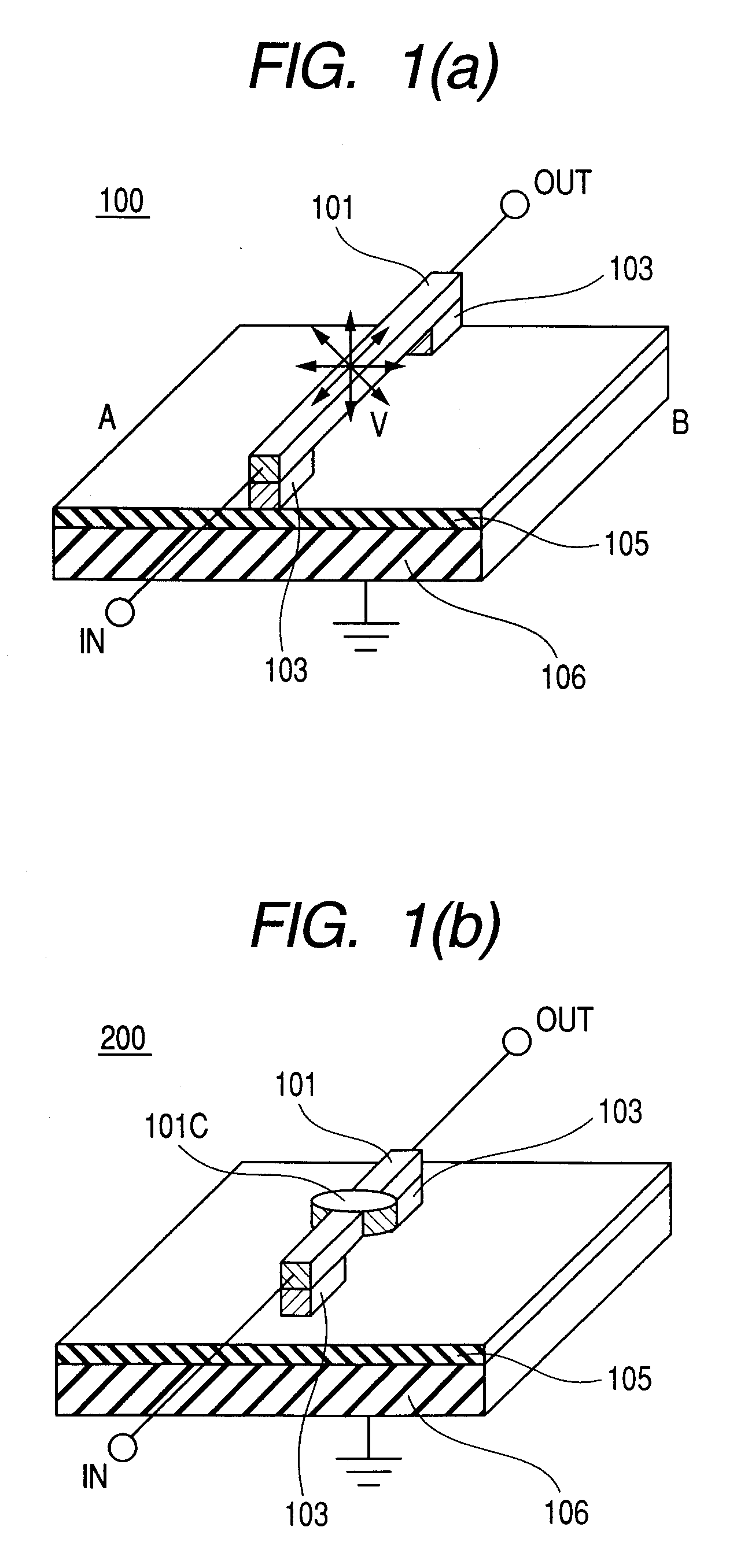
[0089]FIG. 1(a) is a perspective view showing the configuration of an electromechanical signal selection device according to Embodiment 1 of the present invention, in which PrNiO3 is used as a micro-vibrator 101. In the electromechanical signal selection device 100 shown in FIG. 1(a), the micro-vibrator 101 bridged between posts 103 is provided on a substrate 106 having an insulating layer 105 in a surface and connected to the ground. A signal input port IN for signal input and a signal output port OUT for signal output are connected to the micro-vibrator 101. There is formed a mechanism in which when a high frequency signal is input to this signal input port IN, there occurs a potential difference between the micro-vibrator 101 and the substrate 106 so that an electrostatic force is applied to the micro-vibrator 101 with the same frequency as that of the high frequency signal.

[0090] Next, description will be made on the mechanism of signal selection by the micro-vibrator in this e...

embodiment 2

[0132]FIG. 9(a) is a perspective view showing the configuration of an electromechanical signal selection device according to Embodiment 2 of the present invention. In the electromechanical signal selection device 500 shown in FIG. 9(a), a micro-vibrator 101 bridged between posts 103 is provided on a substrate 106 having an insulating layer 105 in the surface. A mechanism for applying an external magnetic field H to the micro-vibrator 101 is provided. A signal input port IN for signal input and a signal output port OUT for signal output are connected to the micro-vibrator 101. The mechanism for applying the external magnetic field H may be a mechanism for generating a magnetic field, such as a magnetic substance or a coil.

[0133] The micro-vibrator 101 is excited by an electrostatic force in the electromechanical signal selection device 100 or 200 according to Embodiment 1. However, the electromechanical signal selection device 500 according to Embodiment 2 uses a different exciting ...

embodiment 3

[0152]FIG. 11(a) is a perspective view showing the configuration of an electromechanical signal selection device according to Embodiment 3 of the present invention. In the electromechanical signal selection device 700 shown in FIG. 11(a), a micro-vibrator 101 bridged between posts 103 and made of PZT, and a signal input electrode 109 provided on a spacer 104 are provided on a substrate 106 having an insulating layer 105 formed in the surface. A signal input port IN for signal input is connected to the signal input electrode 109 and a signal output port OUT for signal output is connected to the micro-vibrator 101. There is formed a mechanism in which when a high frequency signal is input from the signal input port IN, there occurs a potential difference between the signal input electrode 109 and the micro-vibrator 101 so that an electrostatic force is applied to the micro-vibrator 101 with the same frequency as that of the high frequency signal. The vibrating direction of the micro-v...


PUM


Abstract

To provide an electromechanical signal selection device which can be miniaturized and highly integrated and which can selectively output only a signal of a predetermined frequency without providing any sensitive vibration sensing mechanism, and electric equipment using the electromechanical signal selection device. A micro-vibrator serving as a resonator is provided. The micro-vibrator can be excited by an external force to excite vibration of the micro-vibrator. A material whose physical property is changed in accordance with a structural change is used as the micro-vibrator. Thus, a sensitive electromechanical signal selection device is obtained.

Description

TECHNICAL FIELD [0001] The present invention relates to an electromechanical signal selection device including an electromechanical filter, and particularly relates to a micro-vibrator serving as a resonator, a mechanism for exciting the micro-vibrator, or an electromechanical signal selection device in which a material having a physical property variable in accordance with a structural change is used as a micro-vibrator so as to make it possible to adjust the signal selection device characteristic. BACKGROUND ART [0002] With the progress in pervasion of information communication equipment such as wireless terminals, frequencies available for communications have been made broadband dramatically from several millions of hertz for cellular phones or the like to several gigahertz for wireless LAN or the like. Under current conditions, terminals supporting various communication systems are used independently. It is, however, expected to realize a wireless terminal supporting various com...

Claims


Application Information

Patent Timeline
Patent Type & Authority Applications(United States)
IPC IPC(8): H03H9/00B81B3/00H01L41/09H01L41/187H03H3/007H03H9/02H03H9/24H03H9/46H03H9/54
CPCH03H3/0072H03H9/02259H03H2009/02527H03H2009/02496H03H2009/02511H03H9/2463
Inventor NAITO, YASUYUKI
Owner PANASONIC CORP
Why Eureka
Try Eureka