2-Dimensional signal encoding/decoding method and device

a signal and signal technology, applied in the field of two-dimensional signal compression/decompression methods, can solve the problems of block noise in the tile boundary, discontinuous distortion, etc., and achieve the effect of reducing the number of times of store/load increasing the encoding speed, and reducing the number of times of access to a real memory

Inactive Publication Date: 2007-07-19
NEC CORP
View PDF14 Cites 31 Cited by
  • Summary
  • Abstract
  • Description
  • Claims
  • Application Information

AI Technical Summary

Benefits of technology

[0017] In the present invention as described above, coefficients corresponding to the same image position are sequentially read out from the LH, HL, and HH subbands and encoded, so the number of times of store / load to a real memory can be reduced even when a general-purpose sequential CPU is used, and this makes high-speed processing possible. In addition, since coefficients at the same position in the LH, HL, and HH subbands are sequentially encoded at the same time, data of the LH, HL, and HH subbands need not be held until the encoding is completed.
[0018] Also, since sequential encoding can be performed, a high-speed register or cache memory of a CPU can be used as a coefficient memory for storing coefficients to be encoded, and this further increases the encoding speed.
[0019] During decoding, whenever a set of the LH, HL, and HH subband coefficients is decoded, the decoded coefficient values immediately undergo an inverse wavelet operation, thereby reducing the number of times of access to a real memory. In addition, as memory access during decoding, LL subband read is successively performed on the same scan line, and write of the results of the inverse wavelet operation is also successively performed for only two scan lines, thereby increasing the cache memory efficiency. Furthermore, the capacity of an intermediate memory required to temporarily store subbands can be reduced.
[0020] As described above, decoding of a set of the LH, HL, and HH subband coefficients and the inverse wavelet operation of the decoded coefficients can be performed via a high-speed memory such as a register. This makes it possible to increase the speed of decoding even when a general-purpose sequential CPU is used. Also, since subbands need not be entirely stored in an intermediate memory, the memory use amount can be reduced. Furthermore, when parallel processing can be performed by hardware, the decoding speed can be further increased by using the conventional tile dividing method in combination with the present invention.
[0021] Since the processing can be executed at high speed without requiring any special parallel operation hardware, the present invention is effective in an application in which encoding and decoding are performed by a medium-speed to low-speed, general-purpose CPU. This makes it possible to implement a low-cost client terminal which receives and displays images across a network, and an inexpensive ubiquitous terminal.

Problems solved by technology

However, a method which performs wavelet transform after the division into tiles has the problem that a discontinuous distortion, i.e., block noise is produced in the tile boundary.

Method used


Image

  • 2-Dimensional signal encoding/decoding method and device
  • 2-Dimensional signal encoding/decoding method and device
  • 2-Dimensional signal encoding/decoding method and device

Examples


first embodiment

1. First Embodiment

1.1) Encoding Device

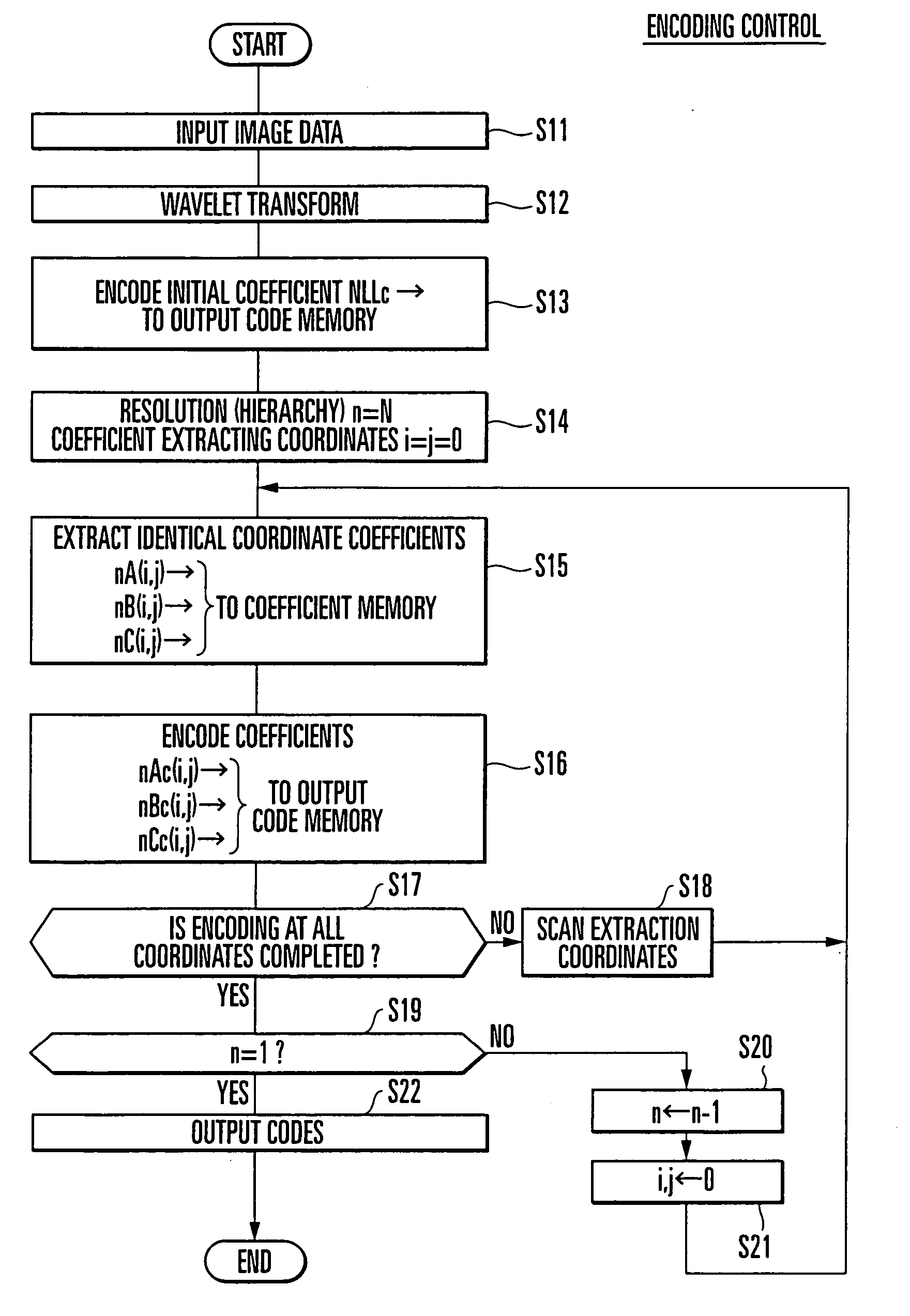
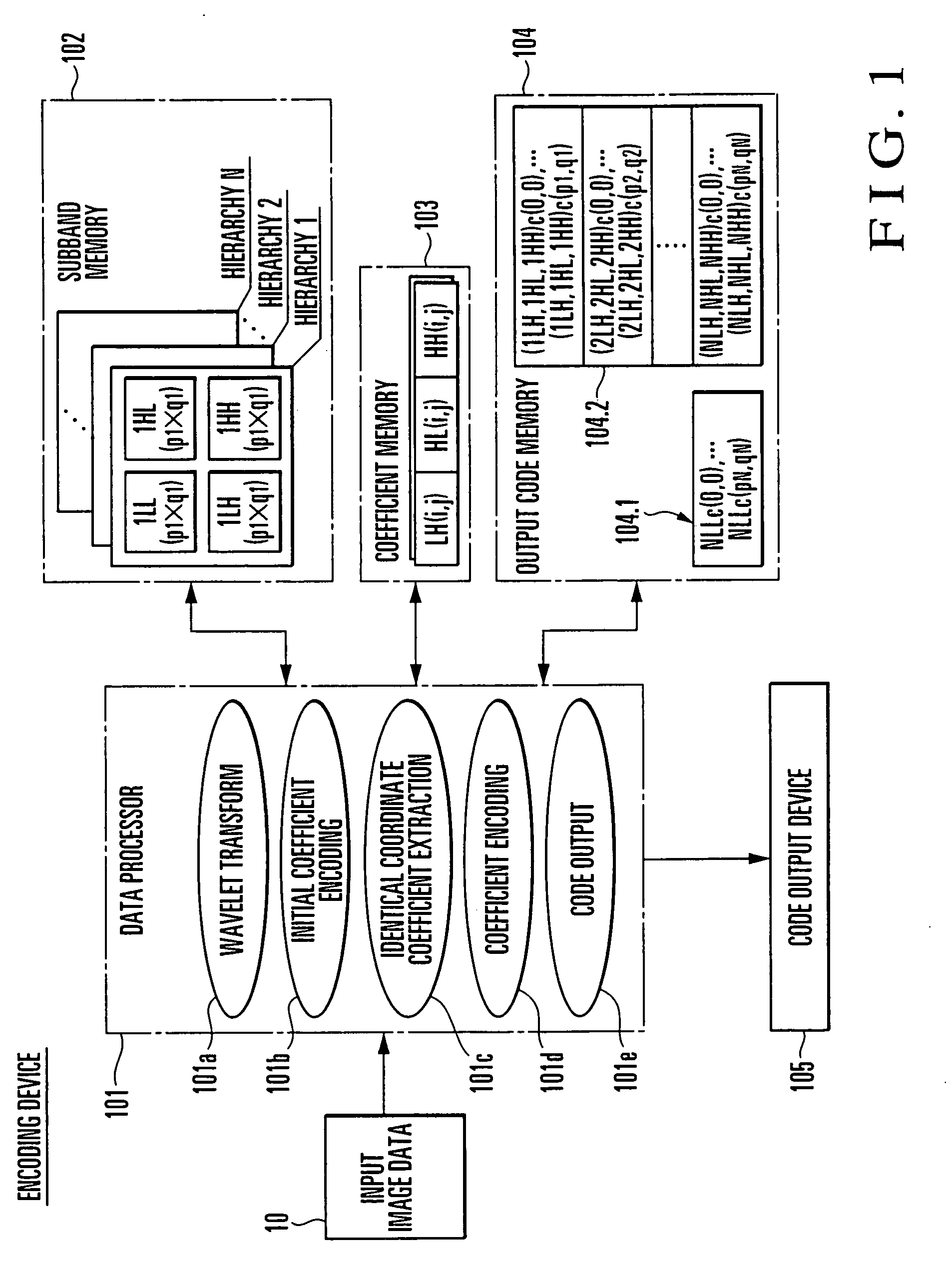
[0048]FIG. 1 is a block diagram showing an outline of the arrangement of an encoding device according to the first embodiment of the present invention. This encoding device receives image data 10 from an image input device (not shown), and outputs a code sequence by wavelet encoding (to be described later). The encoding device mainly comprises a data processor 101, subband memory 102, coefficient memory 103, and output code memory 104, and outputs the generated code sequence to a code output device 105.

[0049] The data processor 101 is a program control processor such as a general CPU (Central Processing Unit), and can generate a wavelet transform (in this embodiment, two-dimensional Haar wavelet transform) process (wavelet transforming means 101a), an initial coefficient encoding process (initial coefficient encoding means 101b), an identical coordinate coefficient extraction process (identical coordinate coefficient extracting means 101c), ...

second embodiment

2. Second Embodiment

2.1) Encoding Device

[0102]FIG. 6 is a block diagram showing an outline of the arrangement of an encoding device according to the second embodiment of the present invention. This encoding device receives image data 10 as a representative example of a two-dimensional signal from an image input device (not shown), and outputs a code sequence by wavelet encoding (to be described later). The encoding device mainly comprises a data processor 301, LL subband memory 302, coefficient memory 303, and output code memory 304, and outputs the generated code sequence to a code output device 305.

[0103] The data processor 301 is a program control processor such as a general CPU, and can generate a pixel extraction process (pixel extracting (element extracting) means 301a), a wavelet transform (in this embodiment, two-dimensional Haar wavelet transform) process (wavelet transforming means 301b), a coefficient encoding process (coefficient encoding means 301c), an initial coeff...

third embodiment

3. Third Embodiment

3.1) Encoding Device

[0145]FIG. 9 is a block diagram showing an outline of the arrangement of an encoding device according to the third embodiment of the present invention. This encoding device receives image data 10 as a representative example of two-dimensional signals from an image input device (not shown), and outputs a code sequence by wavelet encoding (to be described later). The encoding device mainly comprises a data processor 401, LL subband memory 402, coefficient memory 403, output code memory 404, and pixel thinning map memory 405, and outputs the generated code sequence to a code output device 406.

[0146] The data processor 401 is a program control processor such as a general CPU, and can generate a pixel thinning map generation process (pixel thinning map generating means 401a), a pixel thinning extraction process (pixel thinning extracting means 401b), a wavelet transform (in this embodiment, two-dimensional Haar wavelet transform) process (wavelet...


PUM


Abstract

An image is divided into subbands by wavelet transform using the Haar function as the base, and the lowest-frequency LL subband is entirely encoded. LH, HL, and HH subband coefficients which belong to the wavelet decomposition level of each hierarchy are then encoded such that coefficients at the same spatial position are encoded at once. The decoding side first decompresses the lowest-frequency LL subband, and then decodes sets of the LH, HL, and HH coefficients at the same spatial position in the subband of each wavelet decomposition level one by one. The decoding side immediately performs inverse wavelet transform by using the coefficient values, thereby obtaining the LL coefficient value of the next wavelet decomposition level. This makes it possible to sufficiently increase the processing speed even when the wavelet encoding/decoding is performed using a sequential CPU.

Description

TECHNICAL FIELD [0001] The present invention relates to a two-dimensional signal compressing / decompressing method and, more particularly, to a two-dimensional signal encoding / decoding method and device using wavelet transform. BACKGROUND ART [0002] When a two-dimensional signal represented by an image signal is to be stored in a recording medium or transmitted across a network, it is essential to compress or encode the data in order to efficiently use the recording medium or transmission path. Conventionally, various methods such as coding using DCT (Discrete Cosine Transform) and predictive coding have been proposed and used in practice. Recently, information compression methods using wavelet transform are extensively studied, and various proposals are made. [0003] For example, in an encoding / decoding method described in patent reference 1 (Japanese Patent Laid-Open No. 9-148938), a two-dimensional image is first divided into tiles, and wavelet transform is repetitively applied to ...

Claims


Application Information

Patent Timeline
Patent Type & Authority Applications(United States)
IPC IPC(8): G06K9/46H03M7/30H04N19/60H04N1/387H04N1/41H04N1/413H04N19/126H04N19/132H04N19/137H04N19/33H04N19/63H04N19/91H04N19/93
CPCH04N19/63H04N19/124H04N19/132H04N19/14H04N19/59H04N19/17H04N19/1883H04N19/64H04N19/423H04N19/137
Inventor TAKADA, JUN
Owner NEC CORP
Why Eureka
Try Eureka