
Water well pump

a well pump and well pump technology, applied in the direction of radial flow pumps, transverse flow pumps, non-positive displacement fluid engines, etc., can solve the problems of unsatisfactory pump operation, water hammer development, unwanted noise and shaking condition, etc., to achieve the effect of reducing investment, reducing the cost of investment and increasing the efficiency of the pump

Active Publication Date: 2007-07-19
MORELAND JERRY JAY
View PDF11 Cites 16 Cited by
  • Summary
  • Abstract
  • Description
  • Claims
  • Application Information

AI Technical Summary

Benefits of technology

[0019]The pump of the present invention solves these problems by providing a solar-powered, electric submersible turbine pump of a particular kind not previously used in the water well industry for the application presently envisioned. This type pump is referred to herein as the electric submersible regenerative turbine well pump. The efficiency of such a pump is considerably greater than that of centrifugal pumps for the intended applications, and therefore a considerably smaller investment is necessary in cost and space for the solar panels or other forms of power necessary to drive it. Also, the pump of the present invention is adaptable for use with conventional power supplies, and the greater efficiency of the pump insures lower operating costs in such instances.
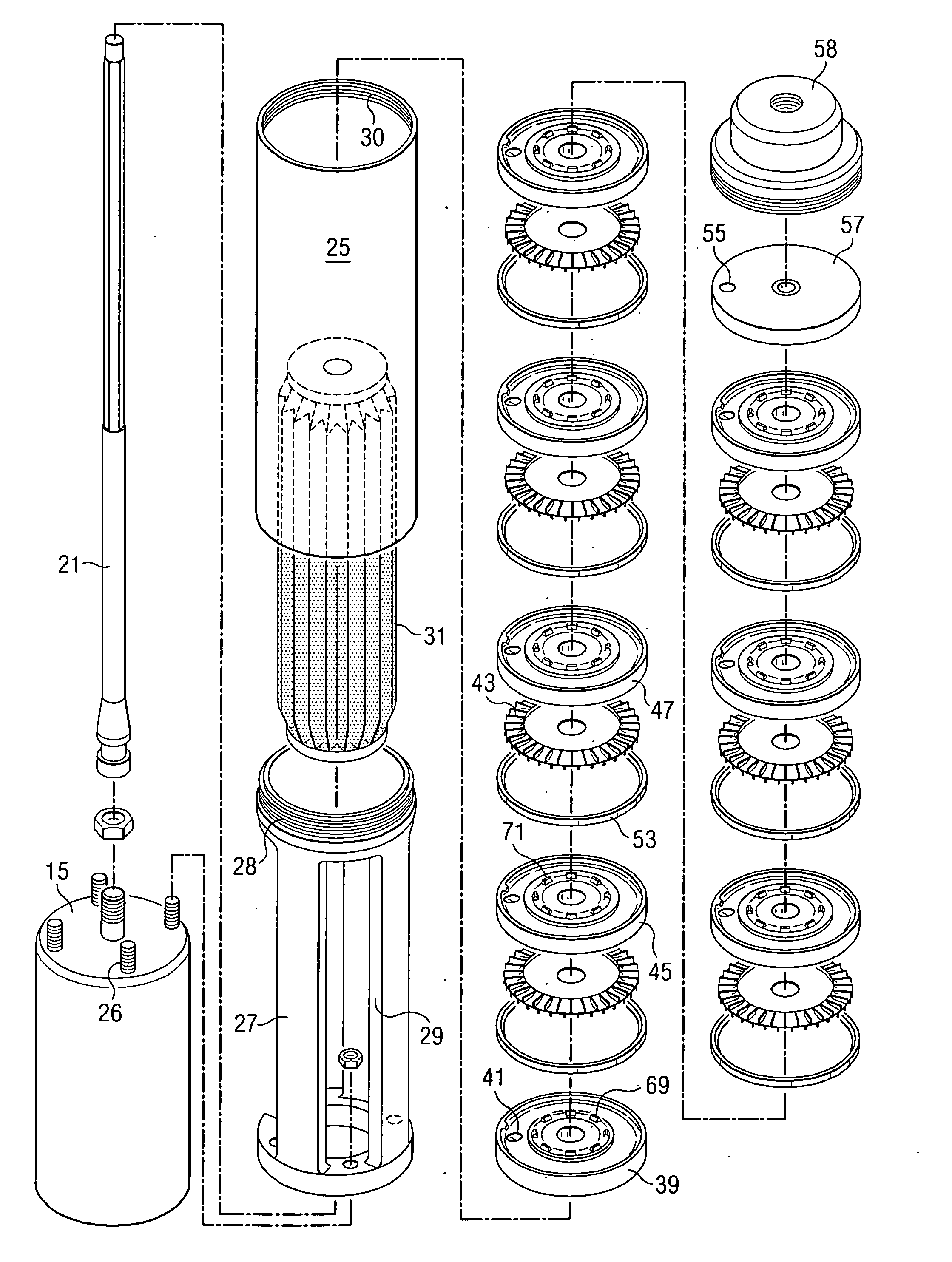
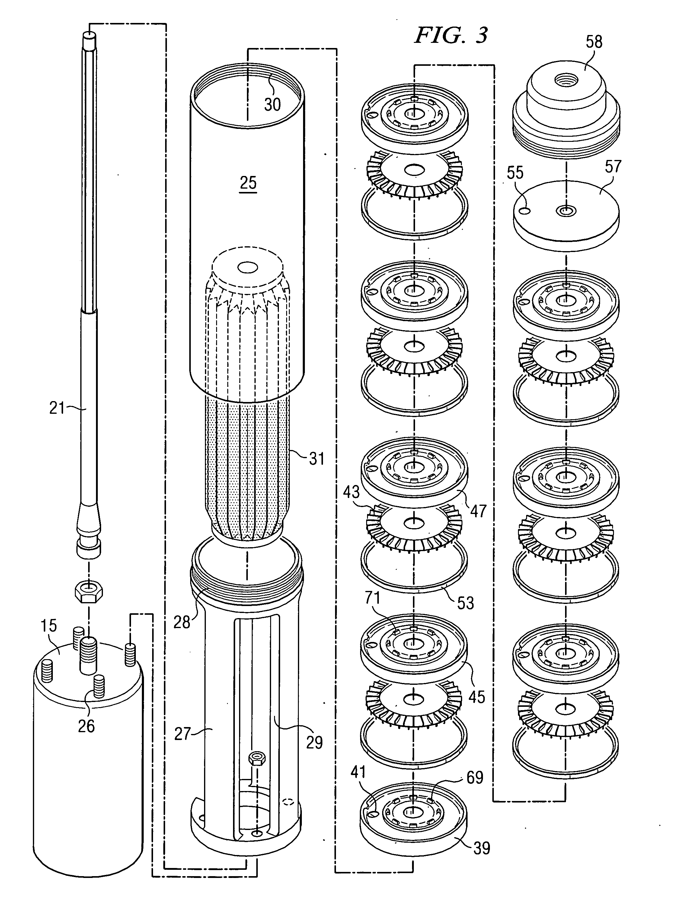
[0022]The regenerative turbine stages form a regenerative turbine section of the pump having an inlet for receiving well water from the suction case and having an outlet port connected to the surface plumbing for supplying well water to the surface location. The regenerative turbine stages include a series of impellers separated by intermediate plates, the impellers having a series of peripheral turbine vanes located on each of opposing sides thereof for moving water through the regenerative turbine section of the pump. Water enters the regenerative turbine section at a inlet location near an outside diameter of each impeller plate, is accelerated about the periphery of the impeller plate before then exiting at a radial location which is at or near the same radial location on the impeller plate as the inlet location. The pump can be conveniently powered from a harvested energy source such as by solar panels or by windmill generated energy sources.
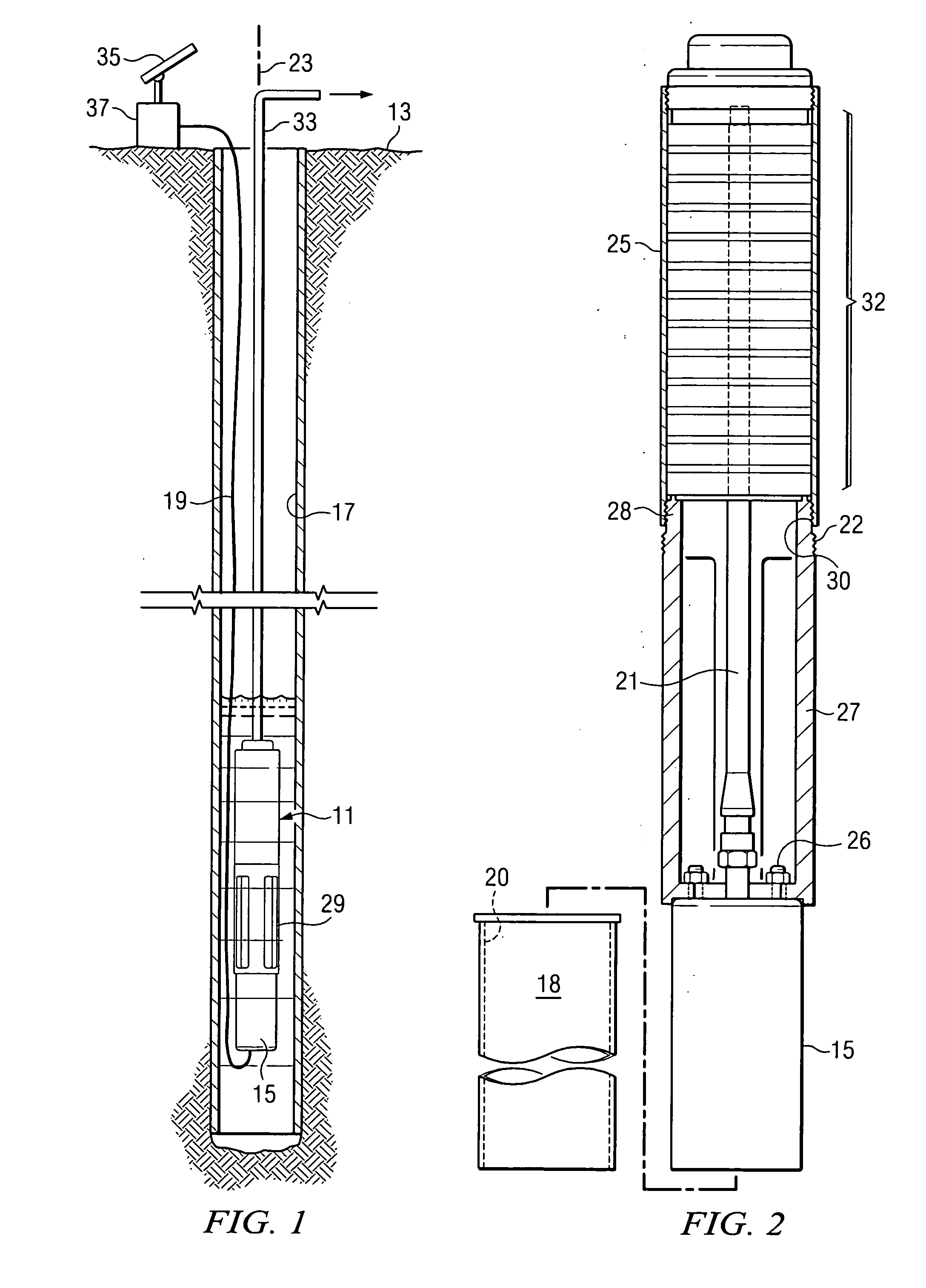
[0025]The improved pump of invention can be used to pump water from a downhole subterranean location within a wellbore to a surface location. The previously described electric submersible pump is located within the wellbore at a selected depth. The supply cable extends from the well surface to the downhole location for supplying electric current to the pump. Associated plumbing runs from the discharge outlet of the pump to the well surface for supplying water to the surface. The pump operates as a multi-stage, regenerative turbine pump which has a plurality of regenerative turbine stages arranged in-line along a vertical axis generally parallel to a central axis of the wellbore. Water enters the regenerative turbine section of the pump at a inlet location near an outside diameter of each impeller, is accelerated about the periphery of the impeller before then exiting at a radial location which is at or near the same radial location on the impeller as the inlet location. Energy is added to the water in a number of impulses by the impeller's vanes as it travels from suction to discharge. The pump can conveniently be powered by a solar panel or other convenient energy source in a high pressure head, low flow application.

Problems solved by technology

In spite of the relatively highly developed state of the art in reciprocating plunger well pumps, certain problems in the operation of these pumps persist.
In particular, when the pumps are stopped, water hammer develops, which is an unwanted noisy and shaking condition of the pump.
Therefore, when the seat that the ball rests on becomes worn and damaged by the constant beating from the ball, erosion from abrasives, corrosion, chipping, or flaking, the steel balls cannot seal the pump and there is unwanted water leakage related to the inability to perform required, specialized service.
In some remote locations, it is not practical to have an electrical power supply from an electric power company.
However, such turbine-type pumps can be inefficient in building a pressure head for a given flow rate and require more electrical power to operate than a positive displacement pump of equivalent capacity.
This is a disadvantage because the solar cells are expensive and more area must be provided to accommodate them.
Efforts to eliminate the above-mentioned shortcomings, while providing a well pump which is relatively inexpensive to manufacture and is reliable in operation, have not been entirely successful and further improvements in such pumps have long been sought.

Method used


Image

  • Water well pump
  • Water well pump
  • Water well pump

Examples


Embodiment Construction

[0038]The present invention utilizes an electric submersible “regenerative” turbine pump as a basis of the water delivery system. The term “regenerative turbine pump” is used as a term of art in the discussion which follows and is specifically intended to distinguish other forms of “turbine” pumps, such as those which operate generally along the lines of centrifugal pumps. Regenerative turbine pumps are sometimes referred to in the same general category of pumps known as centrifugals. While this type of pump does borrow many of its operating principles from the “garden variety” centrifugal pump, the similarities end there because its performance characteristics are substantially different. Regenerative turbine pumps are designed to optimize head rise at relatively low flow conditions. As such, regenerative turbine pumps are sometimes categorized as low specific speed pumps which offer users better head rise and efficiency when compared to standard centrifugal pumps in similar applic...


PUM


Abstract

A water well pump is shown which uses regenerative turbine technology. A submersible electric motor has an output shaft which drives multi-stage regenerative turbine stages of the pump. The various stages are made up of turbine impellers separated by intermediate plates. The turbine impellers have peripheral vanes which cooperate with surrounding scraper rings to form flow channels through the regenerative section of the pump and impart energy to the water passing through the pump. The pump can be powered by a low energy source, such as a solar panel.

Description

CROSS REFERENCE TO RELATED APPLICATIONS[0001]The present applications claims priority from a provisional application Ser. No. 60 / 759,678, filed Jan. 19, 2006, entitled “Lazarus Pump”, by the same inventor.BACKGROUND OF THE INVENTION[0002]1. Field of the Invention[0003]The present invention relates generally to water well pumps and, more specifically, to a vertically-stacked, multi-staged, regenerative turbine pump for a water well which can be solar powered, AC or DC powered, or solar / wind energy powered.[0004]2. Description of the Prior Art[0005]In most rural environments, water wells are a given necessity. Well pumps are the modern day equivalent of windmills, which were historically used to move water from one location or one depth to another. In addition to providing water for such everyday activities as showering, doing laundry and running the dishwasher, well pumps are also used at the present time for such diverse purposes as irrigating crops, providing livestock with water, ...

Claims


Application Information

Patent Timeline
Patent Type & Authority Applications(United States)
IPC IPC(8): F04B17/00
CPCF04D1/063F04D5/006F04D13/06
Inventor MORELAND, JERRY "JAY"
Owner MORELAND JERRY JAY
Learn More