Fuel cell
a fuel cell and cell technology, applied in the field of fuel cells, can solve the problems of increasing power consumption accompanied by the increment of throughput capacity, power consumption has to be reduced, and the energy concentration of lithium-ion cells is coming close to a theoretical limit, so as to improve the availability of devices and the temperature of fuel cells.
- Summary
- Abstract
- Description
- Claims
- Application Information
AI Technical Summary
Benefits of technology
Problems solved by technology
Method used
Image
Examples
first embodiment
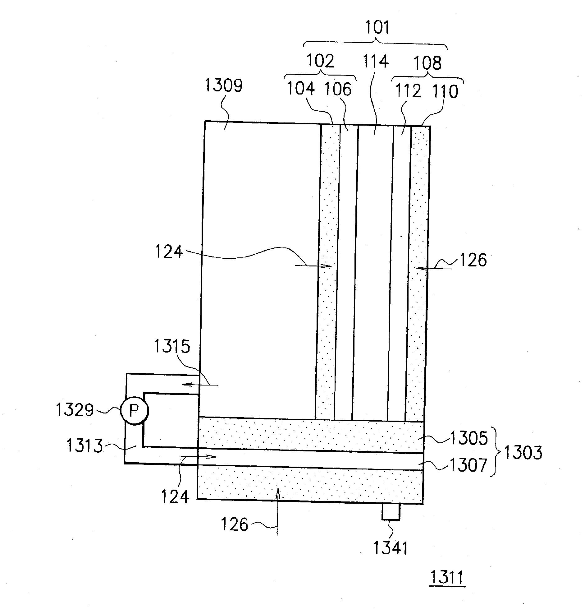
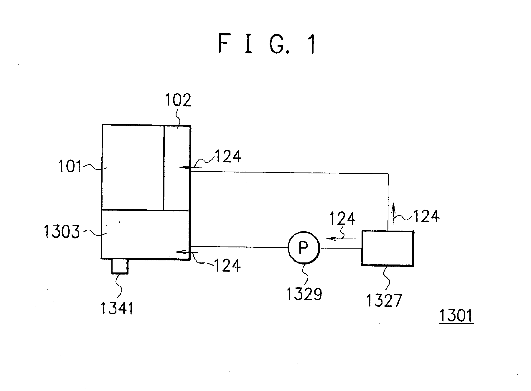
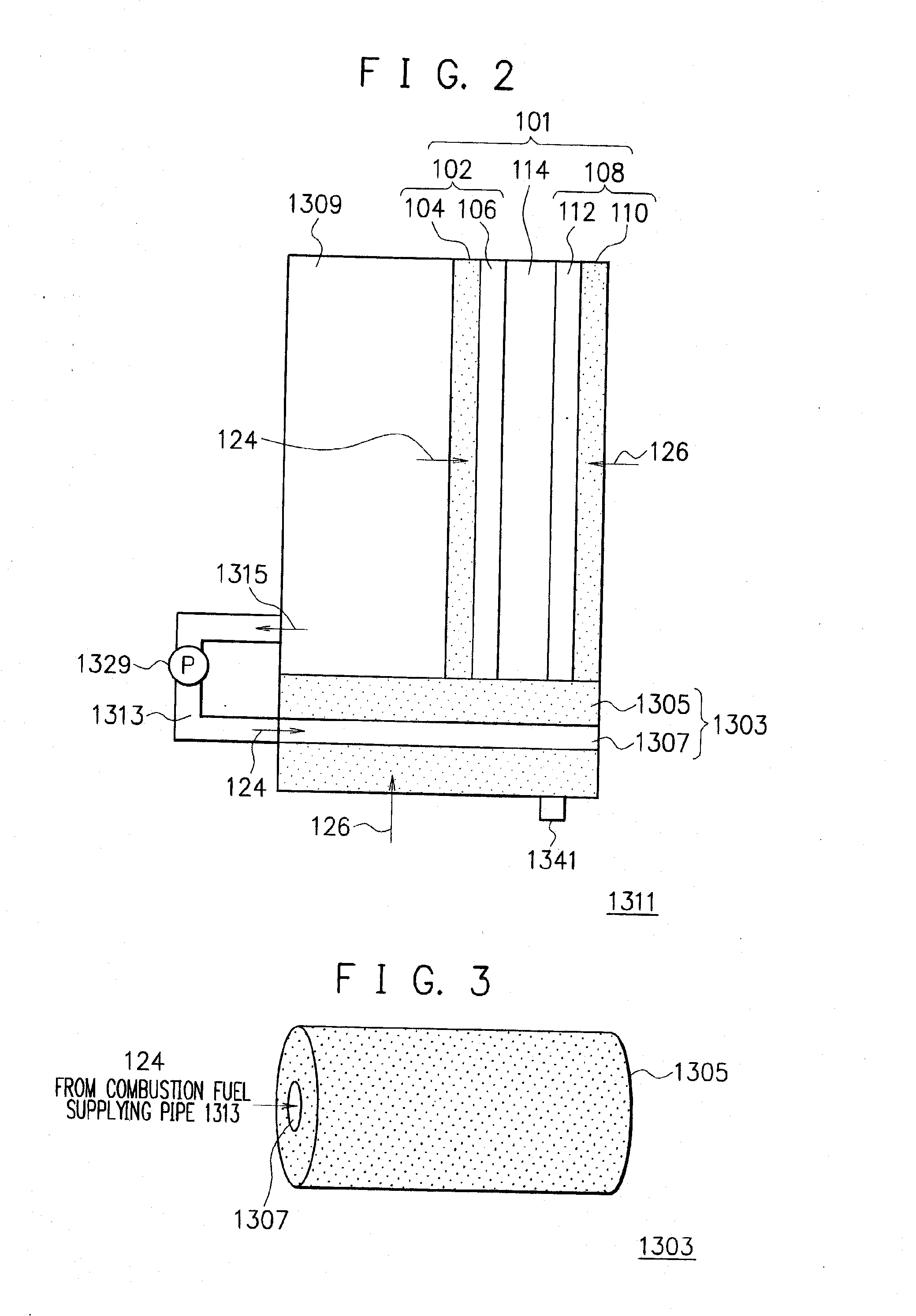
[0037]FIG. 1 is a schematic diagram showing the configuration of a fuel cell according to this embodiment. A fuel cell 1301 shown in FIG. 1 has a unit cell structure 101 and a combustion unit 1303 provided in contact with the unit cell structure 101. The unit cell structure 101 has a fuel electrode 102, an oxidizer electrode (not shown in FIG. 1) and a solid electrolyte membrane (not shown in FIG. 1) that holds them. In addition, the fuel cell 1301 has a fuel tank 1327 and a pump 1329.
[0038] In the fuel cell 1301, fuel 124 contained in the fuel tank 1327 is supplied to the combustion unit 1303 and a unit cell structure 101. In the fuel supplying system at this time, the pump 1329 for controlling the flow of the fuel 124 is provided between the fuel tank 1327 and the combustion unit 1303. Moreover, in the fuel cell shown in FIG. 1, although the pump 1329 is not provided in the fuel supplying line that connects the fuel tank 1327 and the unit cell structure 101, the pump 1329 may be ...
second embodiment
[0092] In a second embodiment, though not shown, a combustion unit 1303 is provided at a side opposite to a fuel electrode 102 of the fuel cell 1301 (shown in FIG. 1) described in the first embodiment, thereby heating an oxidizer electrode not shown in FIG. 1. In addition, in the second embodiment, a fuel cell 1311 (shown in FIG. 2) described in the first embodiment heats the entire configuration member of a unit cell structure 101. Here, in general, when liquid fuel is supplied to the fuel electrode 102, an oxidizer 126 has a smaller heat capacity than the fuel 124. Therefore, heating processes of the fuel electrode 102 and an oxidizer electrode 108 can be different and the oxidizer electrode 108 may be heated more easily. Here, this embodiment shows a way to efficiently heat the unit cell structure 101.
[0093]FIGS. 10 and 11 show the configuration of the fuel cell of this embodiment. FIG. 11 is a cross-sectional view taken along line A-A′ shown in FIG. 10.
[0094] In the fuel cell ...
third embodiment
[0101] In the fuel cell according to the first or second embodiment, a fuel supplying system may have a fuel container retaining a fuel 124 and a high-concentration fuel container retaining a liquid fuel having a concentration higher than that of the fuel 124 supplied to a unit cell structure 101.
[0102]FIG. 13 is a schematic view showing the configuration of the fuel cell according to this embodiment. In the fuel cell shown in FIG. 13, a fuel tank 1327 consists of a low-concentration fuel tank 1333 and a high-concentration fuel tank 1335. In an initial state, the low-concentration fuel tank 1333 is filled with the low-concentration fuel having a concentration suitable for the unit cell structure 101 and the high-concentration fuel tank 1335 is filled with the high-concentration fuel 725 having a fuel component concentration higher than the liquid in the low-concentration fuel tank 1333. Further, in the fuel cell shown in FIGS. 13 and 14 in the third embodiment, although a pump 1329...
PUM
 Abstract
Description
Claims
Application Information
 - R&D
- Intellectual Property
- Life Sciences
- Materials
- Tech Scout
- Unparalleled Data Quality
- Higher Quality Content
- 60% Fewer Hallucinations
Browse by: Latest US Patents, China's latest patents, Technical Efficacy Thesaurus, Application Domain, Technology Topic, Popular Technical Reports.
© 2025 PatSnap. All rights reserved.Legal|Privacy policy|Modern Slavery Act Transparency Statement|Sitemap|About US| Contact US: help@patsnap.com


