Conditioner device for conditioning polishing pad and chemical mechanical polishing apparatus including the same

a technology of mechanical polishing and conditioning polishing, which is applied in the direction of grinding drives, abrasive surface conditioning devices, manufacturing tools, etc., can solve the problems of lowering the conditioning efficiency, increasing stress and impact on the surface the cmp process, and more frequent scratching or defects on the wafers, so as to improve the conditioning efficiency of the polishing pad, improve the mobility of the slurry, and reduce the abrasion of diamond particles

Inactive Publication Date: 2007-07-19
SAMSUNG ELECTRONICS CO LTD
View PDF6 Cites 16 Cited by
  • Summary
  • Abstract
  • Description
  • Claims
  • Application Information

AI Technical Summary

Benefits of technology

[0020]According to the present invention, the changes in the arrangement configurations of the diamond particles enhance the mobility of the slurry, lowering the abrasion of the diamond particles. Thus the conditioning efficiency of the polishing pad is increased and the lifetime of the conditioner device is prolonged. In addition, by adjusting the extrusion heights of the diamond particles, the conditioning efficiency of the polishing pad can be set or maintained as desired.

Problems solved by technology

Accordingly, the stress and impact imparted on the surface of the wafer and the polishing pad during the CMP process are increasing, and in turn scratches or defects on the wafers are occurring more frequently.
The slurry, byproducts of the polishing process, and various kinds of contaminants are deposited on the polishing pad during the CMP process, lowering the conditioning efficiency.
Especially, the abrasion of the diamond particles becomes a much more serious problem for the tungsten slurry that carries the chemicals of a strong acid and the polishing particles of which hardness being no less than that of the diamond particles.
The decrease of the conditioning efficiency to the polishing pad causes many problems such as shortening the lifetime of the conditioner device, deteriorating the reliability of the polishing process, and increasing the process time.

Method used


Image

  • Conditioner device for conditioning polishing pad and chemical mechanical polishing apparatus including the same
  • Conditioner device for conditioning polishing pad and chemical mechanical polishing apparatus including the same
  • Conditioner device for conditioning polishing pad and chemical mechanical polishing apparatus including the same

Examples


Embodiment Construction

[0035]Hereinafter, the embodiments of the present invention will be described below in more detail with reference to the accompanying drawings. The present invention may, however, be embodied in different forms and should not be constricted as limited to the embodiments set forth herein. Rather, these embodiments are provided so that this disclosure will be thorough and complete, and will fully convey the scope of the invention to those skilled in the art.

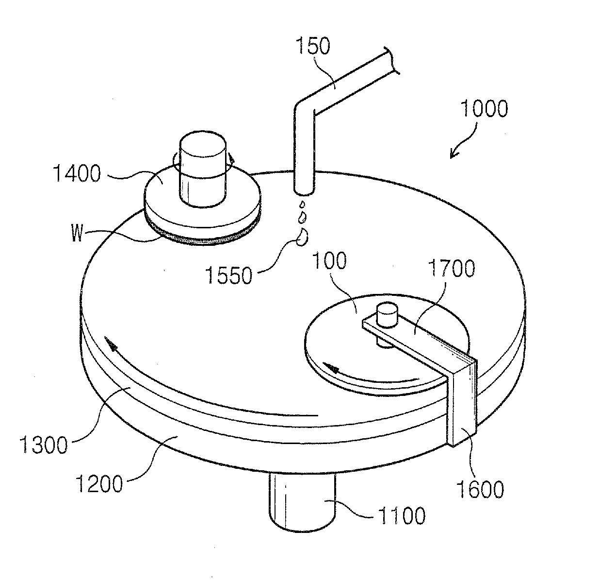
[0036]FIG. 4 is a perspective view illustrating a CMP apparatus including the conditioner device for a polishing pad according to an exemplary embodiment of the present invention. Referring to FIG. 4, the CMP apparatus 1000 used for a CMP process includes a platen 1200 that is a circular rotating table, the platen 1200 being installed on a center axis 1100. It also includes a polishing pad 1300 that is, for example, a pad made of a polymeric material such, such as a urethane material, particularly a hard polymeric material, the pol...


PUM

PropertyMeasurementUnit
diameteraaaaaaaaaa
diametersaaaaaaaaaa
diametersaaaaaaaaaa

Abstract

The present invention relates to a conditioner device for polishing pad and a chemical mechanical polishing (CMP) apparatus having the same. The conditioner device of the present invention comprises a rotable support plate including a support plate surface comprising a center area located about the rotational axis of the support plate, a mid area surrounding the center area, and a peripheral area surrounding the mid area, a plurality of conditioning zones located within a portion of the mid area of the support plate surface. A plurality of hard particles which are densely arranged within the conditioning zones and are attached to the support plate surface. A plurality of passages defined by the conditioning zones within which a slurry flows, the passages occupying a portion of the mid area which is not occupied by the conditioning zones, the center area and the peripheral area.

Description

CROSS-REFERENCE TO RELATED APPLICATIONS[0001]This U.S. non-provisional patent application claims priority under 35 U.S.C. § 119 from Korean Patent Application No. 2005-133590 filed on Dec. 29, 2005, the entire contents of which are hereby incorporated by reference.BACKGROUND[0002]1. Field of the Invention[0003]The present invention relates to an apparatus for manufacturing semiconductor devices. More particularly, the present invention relates to a conditioner device that can maintain a polishing rate of a polishing pad at a sufficient level, and also to a chemical mechanical polishing (CMP) apparatus having the same.[0004]2. Discussion of the Related Art[0005]With the integration density of a semiconductor device increasing, a tiny scratch or defect imposed on a wafer during a CMP process is considered as one of the major factors that deteriorate the productivity and yield in manufacturing the semiconductor device. Especially in the recent semiconductor manufacturing processes whic...

Claims


Application Information

Patent Timeline
Patent Type & Authority Applications(United States)
IPC IPC(8): B24B7/00B24B29/00B24B21/18
CPCB24B53/14B24B53/017H01L21/304
Inventor MOON, SUNG-TAEKLEE, DONG-JUNKANG, KYOUNG-MOONKIM, NAM-SOOAHN, BONG-SU
Owner SAMSUNG ELECTRONICS CO LTD
Why Eureka
Try Eureka