Advanced ceramic heater for substrate processing

Inactive Publication Date: 2007-07-26
COMPONENT RE ENGINEERING COMPANY INC +1
View PDF64 Cites 90 Cited by
  • Summary
  • Abstract
  • Description
  • Claims
  • Application Information

AI Technical Summary

Benefits of technology

[0008]An exemplary susceptor comprises an electrostatic chuck. The electrostatic chuck includes a dielectric plate having an embedded electrode, first and second manifold plates, and a barrier plate disposed between the first and second manifold plates. A surface of the dielectric plate can be concave or convex, in some embodiments. The dielectric plate includes a dielectric material characterized by a first coefficient of thermal expansion, and the barrier plate includes a material characterized by a second coefficient of thermal expansion. The first manifold p

Problems solved by technology

These reactions produce reaction by-products and other effects which can be detrimental to the desired process results.
However, ceramic materials can be mechanically fragile, have limited methods of fabrication due to inherent m

Method used


Image

  • Advanced ceramic heater for substrate processing
  • Advanced ceramic heater for substrate processing
  • Advanced ceramic heater for substrate processing

Examples


Embodiment Construction

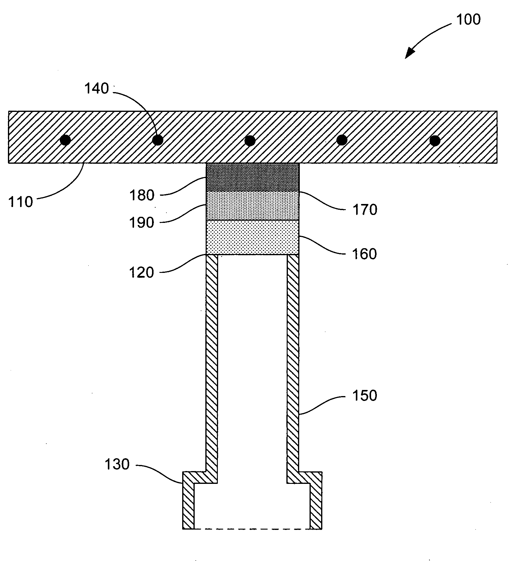
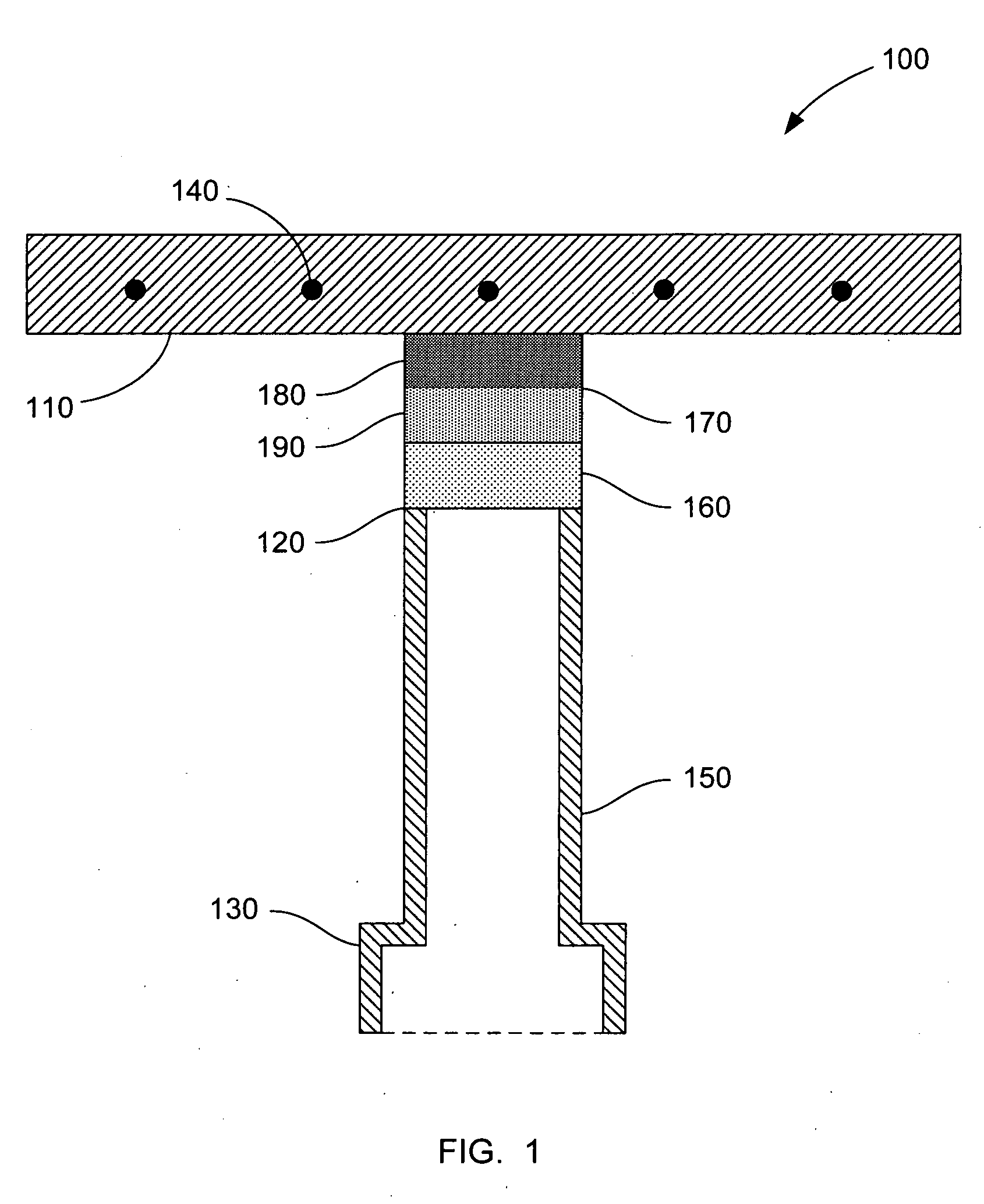
[0015]The present invention provides susceptors that employ layers of CTE-matching materials to reduce the stresses that otherwise lead to cracking and failure with repeated thermal cycling. Exemplary CTE-matching materials include metal alloys of aluminum and silicon that are convenient to machine to desired shapes and can be tailored to specific CTE values by adjusting the ratio of the two elements. For high temperature applications, a susceptor can comprise a CTE-matching material that accommodates the differences in the CTEs of a ceramic material of a substrate support, on one side, and a thermal barrier layer disposed on the other side. The thermal barrier layer thermally shields a metal chamber mount from the heat generated at the substrate support. When these materials are bonded together, such as by diffusion bonding, the resulting susceptor is a monolithic body without sharp interfaces and without bonding or interfacial layers.

[0016]FIG. 1 illustrates a cross-section of an ...


PUM

PropertyMeasurementUnit
Coefficient of linear thermal expansionaaaaaaaaaa
Thermal propertiesaaaaaaaaaa
Thermal expansion coefficientaaaaaaaaaa

Abstract

Susceptors are provided that employ layers of CTE-matching materials to reduce the stresses that otherwise lead to cracking and failure. Exemplary CTE-matching materials include metal alloys of aluminum and silicon that can be tailored to specific CTE values by adjusting the ratio of the elements. An exemplary susceptor comprises a CTE-matching material that accommodates the differences in the CTEs of a ceramic material and a thermal barrier layer disposed on opposite sides of the CTE-matching material. Methods are also provided for forming susceptors. These methods comprise assembling the components and bonding the assembly together, such as by diffusion bonding, to produce a susceptor that is a monolithic body.

Description

CROSS-REFERENCE TO RELATED APPLICATIONS[0001]This application claims priority from U.S. Provisional Patent Application Ser. No. 60 / 761,737, filed Jan. 23, 2006, and entitled “King Electrostatic Chuck,” which is incorporated herein by reference in its entirety.BACKGROUND OF THE INVENTION[0002]1. Field of the Invention[0003]The present invention relates generally to the field of semiconductor fabrication, and more particularly to susceptors for use in processing chambers.[0004]2. Description of Related Art[0005]Semiconductor processing and similar manufacturing processes typically employ thin film deposition techniques such as Chemical Vapor Deposition (CVD), Physical Vapor Deposition (PVD), Vapor Phase Epitaxy (VPE), Reactive Ion Etching, and other typical processing methods. In CVD processing, as well as in other manufacturing techniques, a substrate such as a silicon wafer is secured within a processing chamber by a susceptor and exposed to the particular processing conditions of t...

Claims


Application Information

Patent Timeline
IPC IPC(8): H01L21/306C23C16/00
CPCC23C16/4586C23C16/4581
Inventor ELLIOT, BRENTBALMA, FRANKVEYTSER, ALEXANDERWIDAWSKI OGILVY, ANDREW JOSEFFORREST, JAMES BURNETT
Owner COMPONENT RE ENGINEERING COMPANY INC
Why Eureka
Try Eureka