

Ramp rate blender
a technology of blender and pump rate, which is applied in the direction of liquid handling, instruments, packaged goods types, etc., can solve the problems of high cost of high pressure control valve, difficult to meet the needs of customers, and difficult to adapt to the delivery of hydrogen and other compressed gases. achieve good control of temperature, good control of pressure, and avoid costly and unreliable mechanical compression
- Summary
- Abstract
- Description
- Claims
- Application Information
AI Technical Summary
Benefits of technology
Problems solved by technology
Method used
Image

Examples
example 1
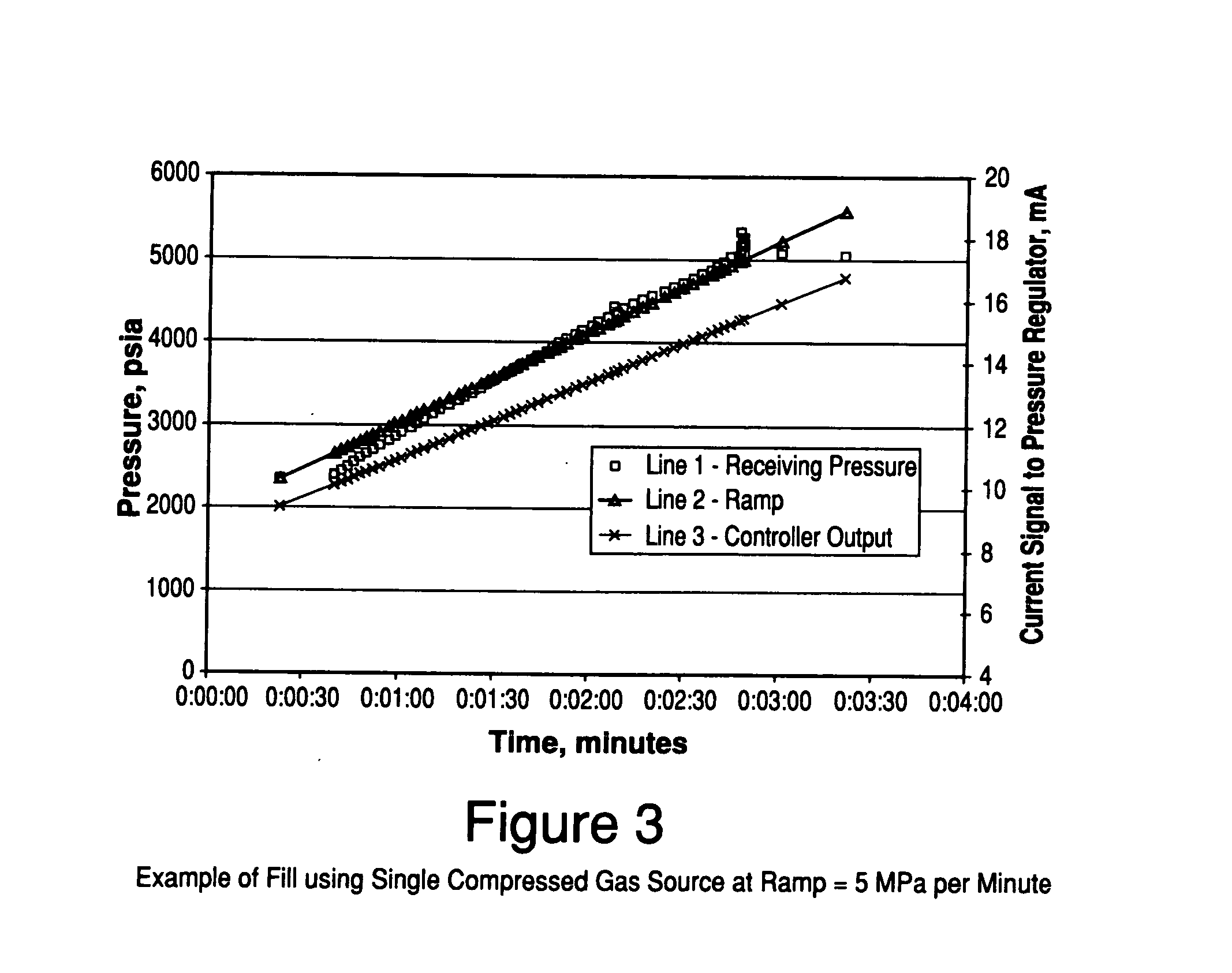
[0068]FIG. 3 illustrates data from an actual fill of a receiving vessel by a single compressed hydrogen stream in accordance with a process that was configured as shown in FIG. 1 and in which only gas from Gas Supply 1 of FIG. 1 was fed to receiving vessel 27. The ramp rate of Gas Supply 1 was 5 MPa per minute. The actual rise in pressure in the receiving vessel (Line 1 of FIG. 3) tracks closely with the desired ramp rate (Line 2 of FIG. 3). Due to the system dynamics, the value of pressure at any time can be either less than (in FIG. 3, at times less than about 1.5 minutes) or greater than (in FIG. 3, at times greater than 2 minutes) the desired ramp rate. The output from the controller to the pressure regulator (Line 3 of FIG. 3) continues to increase over the filling process due to the decrease in pressure driving force between the supply pressure (between 5,000 and 6,000 psia) and the pressure in the receiving vessel. Adjustments are made by the controller (in this case, a progr...
example 2
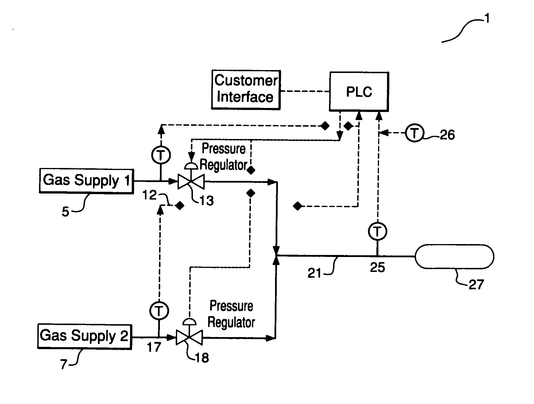
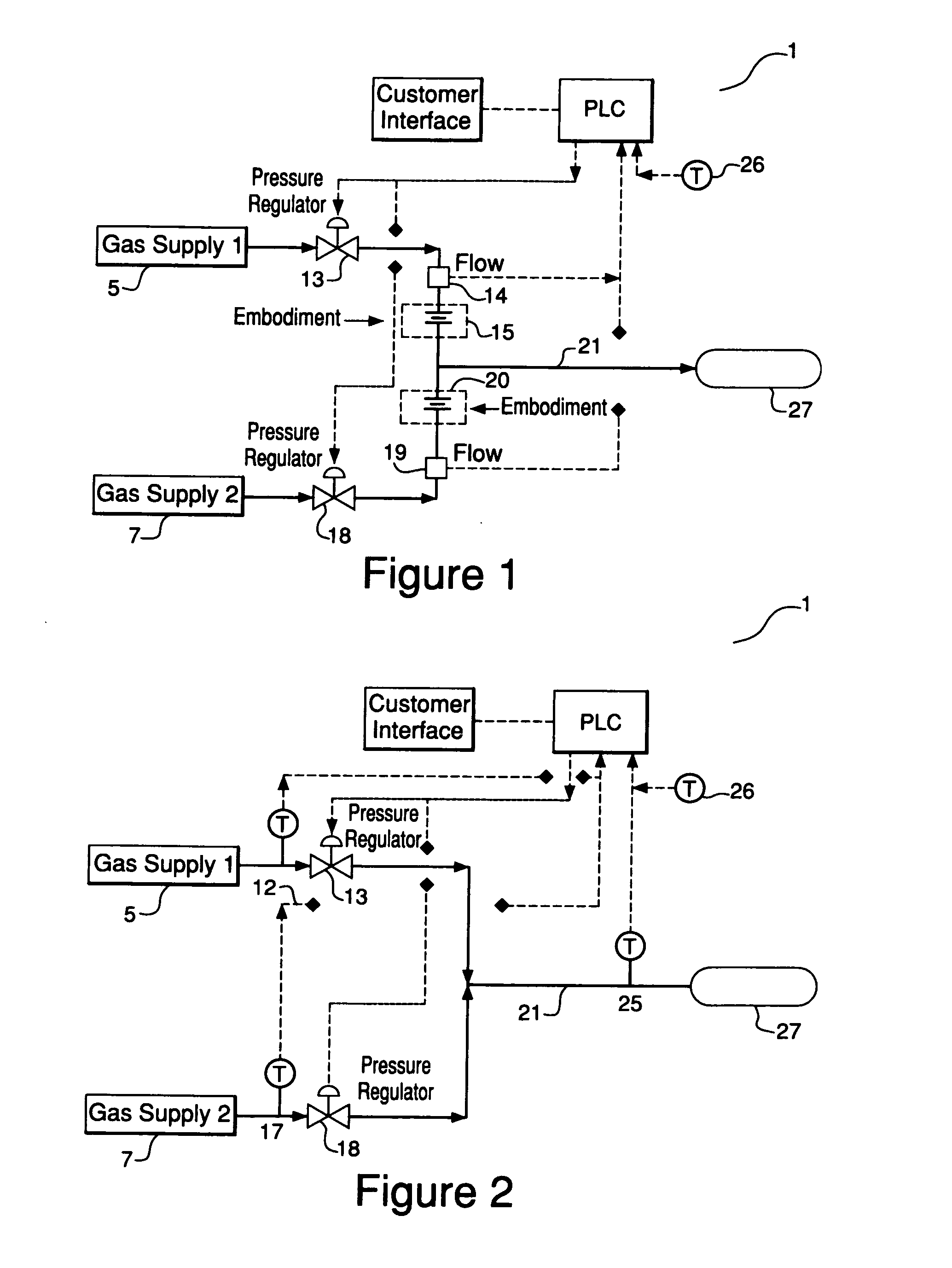
[0069] A process configured in accordance with FIG. 1, in which a receiving vessel was filled with a blend of compressed natural gas (CNG) and hydrogen, was modeled using both the National Institute of Standards thermodynamic data base of pure fluids (NIST Standard Reference Database 23) and the data illustrated in FIG. 3. The model assumed that all of the components of FIG. 1 were used except for restrictive orifice plates 15 and 20.
[0070]FIG. 4 shows the calculated response of a system at ramp rates that achieve a mass ratio of hydrogen to CNG in the receiving vessel of 6%.
[0071]FIG. 5 illustrates estimated cumulative quantities (in units of mass) for both CNG (Line 1 of FIG. 5) and hydrogen (Line 2 of FIG. 5) over the fill time, the estimated mass ratio of hydrogen at any time during the filling process (Line 3 of FIG. 5), and the desired mass ratio of hydrogen (Line 4 of FIG. 5). The output from the controller to the two pressure regulators (Line 3 for H2 and Line 4 for CNG in...
example 3
[0073] A process configured in accordance with FIG. 1 in which a receiving vessel was filled with a blend of two hydrogen streams having different temperatures was modeled using NIST Standard Reference Database 23 and the data illustrated in FIG. 3. The model assumed that all of the components of FIG. 1 were used and that the temperatures of the two hydrogen streams were 70° F. and −40° F., respectively.
[0074]FIG. 6 illustrates the variation of ramp rate and temperature under conditions which achieve a desired temperature in the receiving vessel of 30° F.
[0075]FIG. 7 illustrates estimated instantaneous quantities for both warm hydrogen (Line 1 of FIG. 7) and cold hydrogen (Line 2 of FIG. 7) over the fill time, the calculated temperature of hydrogen in the receiving vessel at any time during the filling process (Line 3 of FIG. 7), and the desired temperature of hydrogen (Line 4 of FIG. 7). The output from the controller to the two pressure regulators (Line 3 for warm hydrogen and L...
PUM
| Property | Measurement | Unit |
|---|---|---|
| Temperature | aaaaa | aaaaa |
| Temperature | aaaaa | aaaaa |
| Temperature | aaaaa | aaaaa |
Abstract
Description
Claims
Application Information