Soft magnetic material and dust core

a soft magnetic material and dust core technology, applied in the direction of magnetic bodies, cores/yokes, ferroso-ferric oxides, etc., can solve the problems of general difficulty in removal of impurity phases, reduce the stress-strain induced by surface energy relative to the whole metal magnetic particle, and reduce the stress-strain induced by surface energy. the effect of the stress-strain ratio

Inactive Publication Date: 2007-07-26
SUMITOMO ELECTRIC IND LTD
View PDF5 Cites 11 Cited by
  • Summary
  • Abstract
  • Description
  • Claims
  • Application Information

AI Technical Summary

Benefits of technology

[0010] In the thus constituted soft magnetic material, iron oxides such as FeO, Fe2O3, or Fe3O4, which are formed by the reaction between iron and oxygen, in the metal magnetic particles are contained. FeO and Fe2O3 are nonmagnetic compounds, and Fe3O4 is a magnetic compound but is low in magnetic flux density compared with that of Fe, so that these iron oxides decrease the magnetic flux density of the soft magnetic material.
[0017] More preferably, the coercive force of the dust core is 2.0×10² A / m or less. According to the thus constituted dust core, the iron loss of the dust core can be sufficiently reduced even in a low-frequency region and the dust core produced using the soft magnetic material can be utilized regardless of the frequency to be applied.

Problems solved by technology

Among them, strains such as defects or dislocation can be reduced by carrying out thermal treatment, but the impurity phases are generally difficult to remove by thermal diffusion.

Method used


Image

  • Soft magnetic material and dust core
  • Soft magnetic material and dust core
  • Soft magnetic material and dust core

Examples


example 1

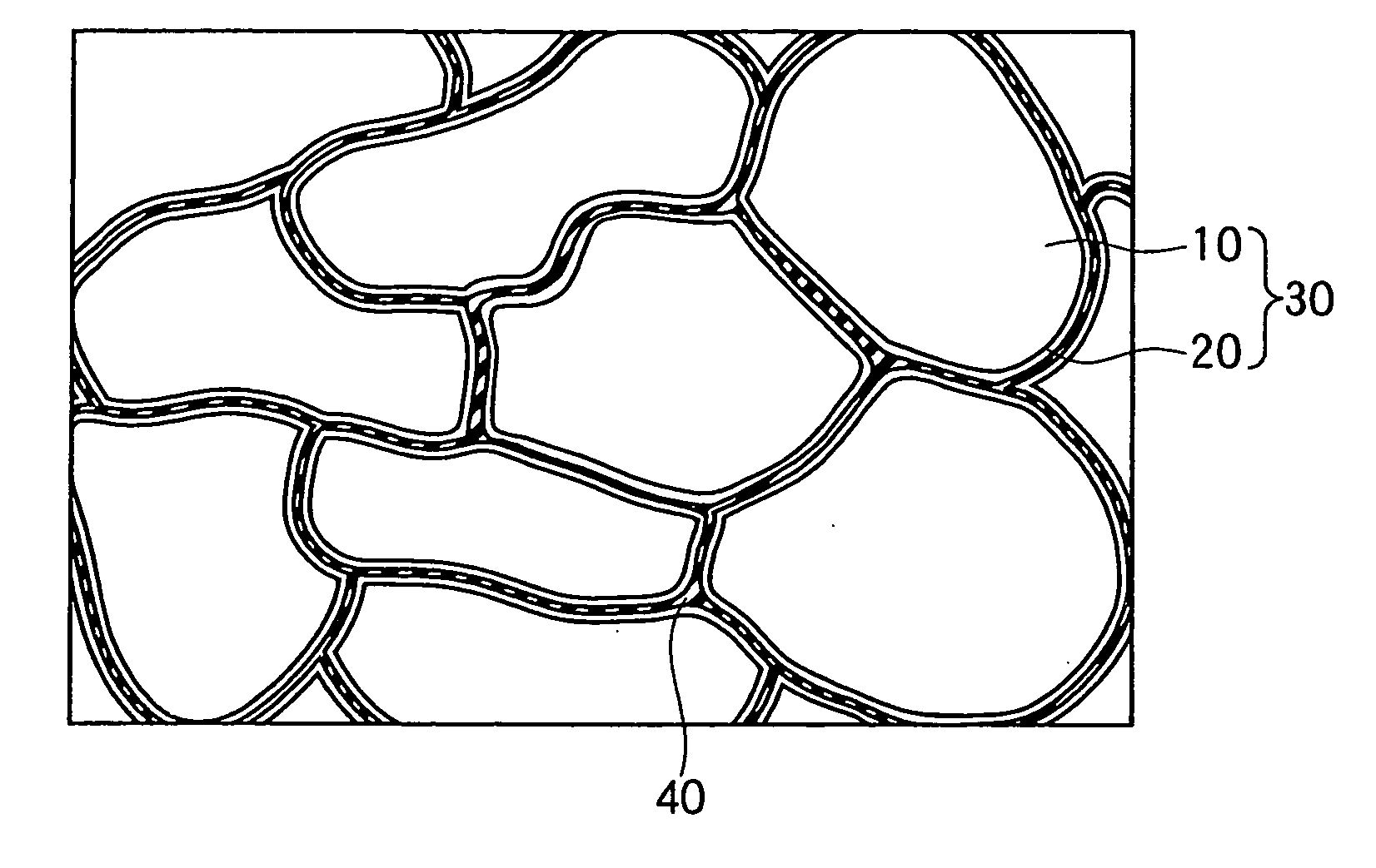
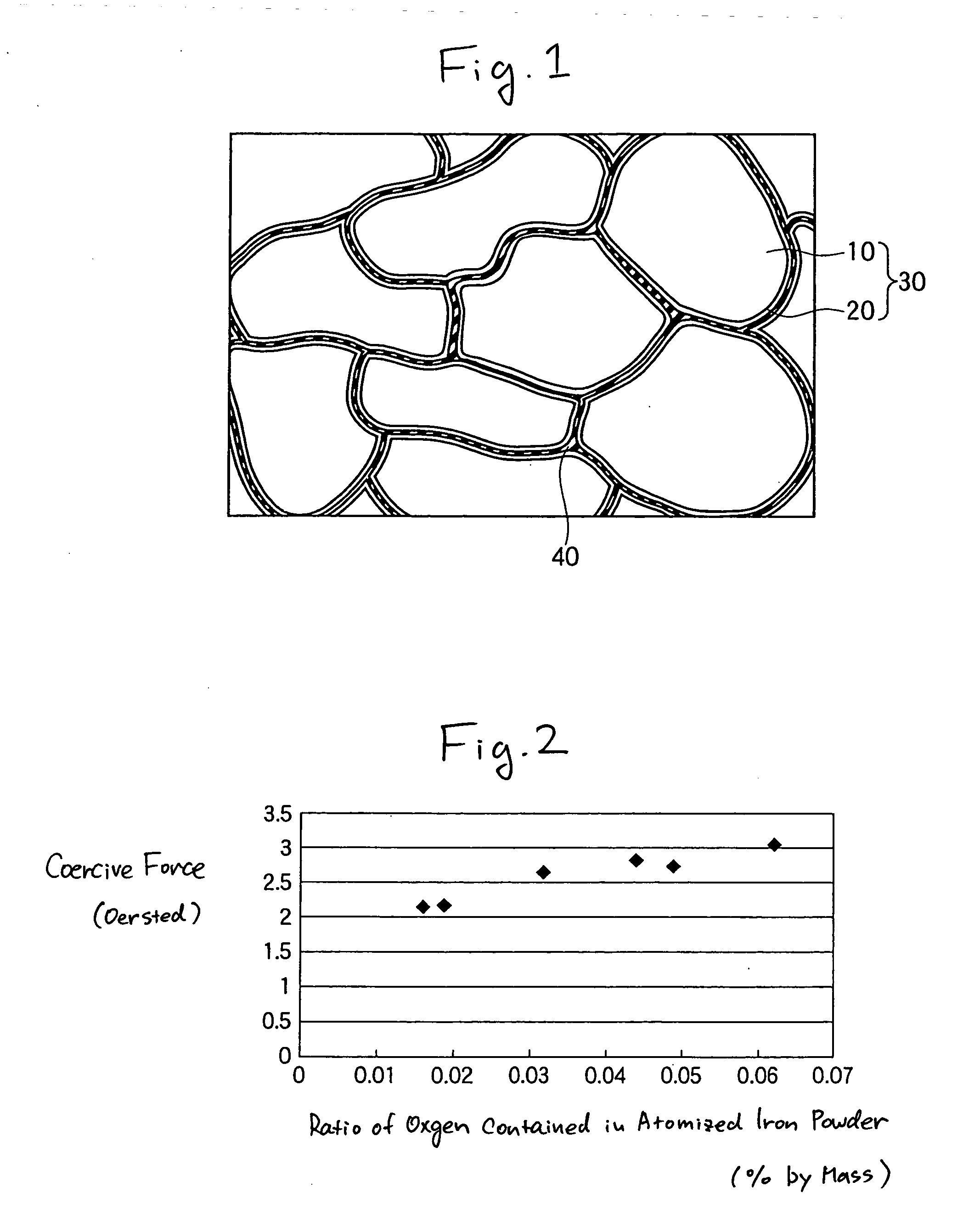
[0043] First, an atomized iron powder to be metal magnetic particles 10 in FIG. 1 was prepared. When the particle size distribution of the atomized powder was measured using a laser scattering diffractometry, the average particle size of the atomized iron powder was found to be 200 μm. Then, the atomized iron powder was placed in an atmosphere of a mixed gas composed of hydrogen and argon and reductive annealing was carried out under conditions of a temperature of 800° C. and 3 hours. On this occasion, the partial pressure of hydrogen relative to the total pressure of the mixed gas 1.01×10⁵ Pa (=1.0 atm) was changed within the range of from 1.01×10⁴ Pa (=0.1 atm) to 1.01×10⁵ Pa. Thereby, in the atomized iron powders of Samples 1 to 6, the ratio of oxygen contained was adjusted.

[0044] Using an inductively coupled plasma-mass spectrometry, compositional analysis of the atomized iron powders of Samples 1 to 6 was carried out with respect to O, C, P, and S. Furthermore, a pellet (diame...

example 2

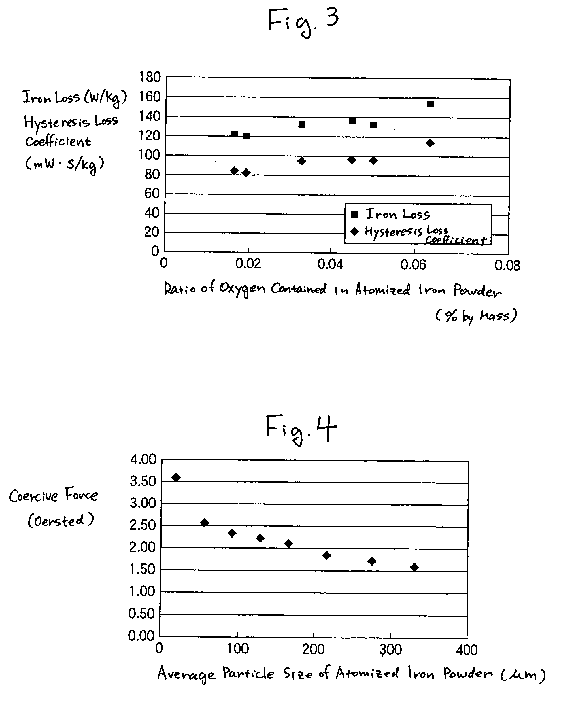
[0051] Subsequently, atomized iron powders having different average particle sizes (the composition was the same as in the atomized iron powder of Sample 1 in Example 1) were prepared and the coercive force of each of the atmized iron powders was measured using the same method as in Example 1. Also, for comparison, the coercive force of the atomized iron powder “Somaloy 500” having an average particle size of 90 μm and manufactured by Hoganas was measured. Table 3 shows the values of the coercive force obtained by the measurement, on every average particle size of the atomized iron powders. FIG. 4 is a graph showing the relationship between the average particle size and coercive force of the atomized iron powders in Example 2 of the invention.

TABLE 3Average particle size of atomized iron powder (μm)90 (“Somaloy500” mfd. by17.55590.5128165215275327.5Hoganas)Coercive3.602.622.382.262.131.871.751.613.60force(oersted)

[0052] As understood with reference to Table 3, as compared with the...


PUM

PropertyMeasurementUnit
coercive forceaaaaaaaaaa
particle sizeaaaaaaaaaa
particle size distributionaaaaaaaaaa

Abstract

An object of the present invention is to provide a soft magnetic material exhibiting excellent magnetic characteristics regardless of the frequency to be applied and a dust core produced from the soft magnetic material. The means for solving the invention is a soft magnetic material that comprises metal magnetic particles 10 containing iron and oxygen. The ratio of oxygen contained in metal magnetic particles 10 is more than 0 and less than 0.05% by mass. A dust core produced using such a soft magnetic material has a coercive force of 2.0×10² A / m or less.

Description

TECHNICAL FIELD [0001] The present invention relates to a soft magnetic material and a dust core. More specifically, it relates to a soft magnetic material for use in choke coils, motor cores, electromagnetic solenoids, and the like, and a dust core produced from the soft magnetic material. BACKGROUND ART [0002] Hitherto, an increase in density and a decrease in size have been attempted in electrical and electronic components, such as motor cores and transformer cores. Further, accurate control and low power performance have been required. For this reason, soft magnetic materials that have excellent magnetic characteristics have been developed for use in the production of these electrical and electronic components. [0003] With regard to dust cores produced using such soft magnetic materials, for example, JP-A-8-269501 discloses a high-frequency dust core, an iron powder for the high-frequency dust core, and processes for producing the same for the purpose of realizing a high AC init...

Claims


Application Information

Patent Timeline
Patent Type & Authority Applications(United States)
IPC IPC(8): H01F1/24B22F1/145B22F1/16C22C38/00H01F1/33H01F3/08
CPCB22F1/0088B22F1/02B22F2998/10B22F2999/00H01F1/24H01F1/33H01F3/08B22F9/082B22F1/0085B22F2201/013B22F2201/11B22F1/145B22F1/16B22F1/142
Inventor KUGAI, HIROKAZUIGARASHI, NAOTOMAEDA, TORUHIROSE, KAZUHIROTOYODA, HARUHISAMIMURA, KOJINISHIOKA, TAKAO
Owner SUMITOMO ELECTRIC IND LTD
Why Eureka
Try Eureka