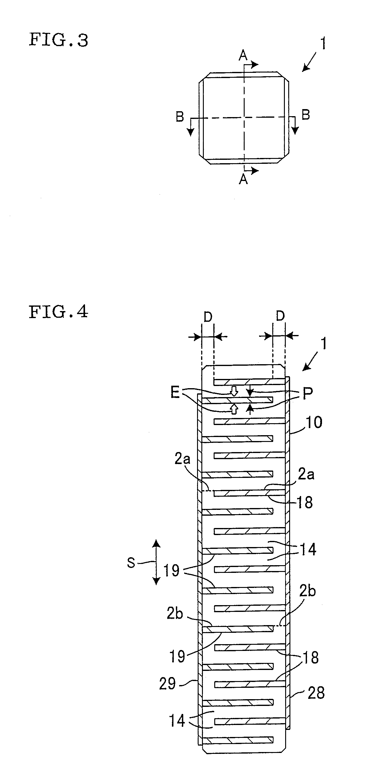
[0031]In the laminated piezoelectric / electrostrictive device of the present invention, even in a case where the total number of the piezoelectric / electrostrictive layers is increased, when the cracks are generated in the interfacial direction (in other words, between the layers), the inner stress can be prevented from being increased. In a case where the number of the layers is small, since the strain is shared by the active portion and the inactive portion, the stress is reduced. When the number of the layers increases, however, the inactive portion undergoes a greater part of the strain, and a large stress is generated in the inactive portion. When the cracks are generated in the interfacial direction (between the layers), continuity of a structure is broken, and a plurality of blocks having the small number of the layers are connected to one another. That is, when the number of the layers is small, the stress is distributed in an only region closest to a boundary between the inactive portion and the active portion. Therefore, a volume of the active portion concerned with the
stress distribution is substantially equal to that of the inactive portion concerned with the
stress distribution. On the other hand, in a case where the number of the layers is large, since the stress is distributed from the boundary between the inactive portion and the active portion to a region distant from the boundary, the volume of the active portion concerned with the
stress distribution becomes larger than that of the inactive portion concerned with the stress distribution, and a
large strain is generated in the inactive portion.
[0032]In the laminated piezoelectric / electrostrictive device or the
actuator described in Patent Documents 1 to 3, a stress relaxing portion (
Patent Document 1), an insulating article (
Patent Document 2) or an
adhesive layer (
Patent Document 3) works as a buffer material or an absorption material to relax or absorb the stress, and prevents the cracks from being generated. Therefore, when the cracks are once generated owing to the inner stress, the presence of each member that works as the buffer material or the absorption material might be a factor for the generation of the cracks which break the piezoelectric / electrostrictive layers or which range across the layers. When the cracks are generated in the boundary between the inactive portion and the active portion of a certain layer, the stress of a distant end of the boundary is isotropically generated, and a development direction of the cracks cannot be specified. Therefore, in these devices or actuators, when a force in excess of a capability of buffering or absorbing the stress works, the driving might be impossible. According to the laminated piezoelectric / electrostrictive device of the present invention, however, such a problem does not occur. This is because the laminated piezoelectric / electrostrictive device of the present invention does not originally buffer or absorb the stress, and the device induces the development direction of the cracks which could be generated owing to the stress toward a predetermined interface to control the cracks. The laminated piezoelectric / electrostrictive device of the present invention can stably operate for the long period even while the cracks are generated. It can be said that the piezoelectric / electrostrictive device is highly reliable over the long period, and has a high durability.
[0033]According to the preferable mode of the laminated piezoelectric / electrostrictive device in the present invention, the specific interval satisfies Equations (1) and (2) described above, and is conditioned by these equations represented by a ratio between a portion in which the expansion / contraction displacement is generated and a portion in which any expansion / contraction displacement is not generated, the thickness of the piezoelectric / electrostrictive layer, the Young's modulus of the piezoelectric / electrostrictive material constituting the piezoelectric / electrostrictive layers and the like. Moreover, there is a restriction on the maximum number of the piezoelectric / electrostrictive layers of one block. Therefore, the cracks are not easily generated in the interfaces present in one block and having the relatively high interface strength, and are easily generated in the interfacial direction in the only interfaces that determine the block and that have the relatively low interface strength. Therefore, regardless of the whole number of the laminated piezoelectric / electrostrictive layers of the laminated piezoelectric / electrostrictive device, the cracks which break the piezoelectric / electrostrictive layers or which range across the piezoelectric / electrostrictive layers can be prevented from being generated. That is, according to the present invention, even in the piezoelectric / electrostrictive device having the large number of the laminated piezoelectric / electrostrictive layers requiring a large displacement amount, a high reliability over the long period is secured. It is possible to realize the laminated piezoelectric / electrostrictive device having both the high durability and a high performance.
[0036]In the laminated piezoelectric
actuator described in Patent Document 3, since a layer (
adhesive layer) having a small
elastic modulus is disposed, it is difficult to design the
actuator so as to increase a generation force (force by which the actuator pushes an object such as a valve of a fuel jet
nozzle) which is an important original characteristic of the actuator. Moreover, since a structure of the actuator is complicated, manufacturing steps increase, and manufacturing costs easily rise. According to the laminated piezoelectric / electrostrictive device of the present invention, however, such a problem does not occur. This is because the laminated piezoelectric / electrostrictive device of the present invention does not have any layer having the small
elastic modulus, and can easily be prepared by the green sheet laminating method.
[0037]In the fuel jet device in which the laminated piezoelectric / electrostrictive device of the present invention is employed as the driving source for operating the opening / closing mechanism of the jet
nozzle, high-speed opening / closing of the jet
nozzle can be realized stably over the long period without making the driving impossible. Therefore, in the fuel jet device in which the laminated piezoelectric / electrostrictive device of the present invention is employed, an optimum amount of the fuel can be fed into a cylinder in accordance with an operating situation of the
internal combustion engine including a
diesel engine. Harmful substances such as
particulates,
nitrogen oxide,
carbon monoxide and hydrocarbons included in an
exhaust gas of the
internal combustion engine are reduced, fuel consumption is reduced, an engine sound is turned down and an engine output is enhanced. Such excellent effects are stably brought about to the engine over the long period.


