Notch filter for ripple reduction in chopper stabilized amplifiers

Active Publication Date: 2007-07-26
TEXAS INSTR INC
View PDF4 Cites 38 Cited by
  • Summary
  • Abstract
  • Description
  • Claims
  • Application Information

AI Technical Summary

Benefits of technology

[0013] In the described embodiment, the first (16A), third (16B), sixth (21B) and eighth (21D) switches are controlled by a first clock signal (Phase3) and the second (21A), fourth (21C), fifth (16C), and seventh (16D) switches are controlled by a second clock signal (Phase4), wherein the first (Phase3) and second (Phase4) clock signals are out of phase with each other, and wherein transitions of the first (Phase3) and second (Phase4) clock signals are staggered with respect to transitions of a chopping signal of the second chopper circuitry (10). The notch filter (15) operates synchronously with a chopping signal of the second chopper circuitry (10) to cause a current at the input (14A,B) of the notch filter (15) to be integrated onto the first integrate and transfer capacitor (C5) during the first clock signal (Phase3) and onto the second integrate and transfer capacitor (C

Problems solved by technology

However, the improved design techniques used in modern chopper-stabilized operational amplifiers and auto-zero operational amplifiers result in trade-offs between input referred noise and quiescent supply current (Iq).
While the auto-zeroing method provides low ripple noise at the amplifier output, its in-band noise is high due to aliasing or noise folding.
On the other hand, the chopper stabilization technique presents lower in-band noise due to absence of noise folding, but its output ripple noise is relatively higher.
Basic chopper-stabilized amplifiers maintain the broadband noise characteristics of their input stages, but “shift” their input offset voltages up to the chopping frequency, cre

Method used


Image

  • Notch filter for ripple reduction in chopper stabilized amplifiers
  • Notch filter for ripple reduction in chopper stabilized amplifiers
  • Notch filter for ripple reduction in chopper stabilized amplifiers

Examples


Embodiment Construction

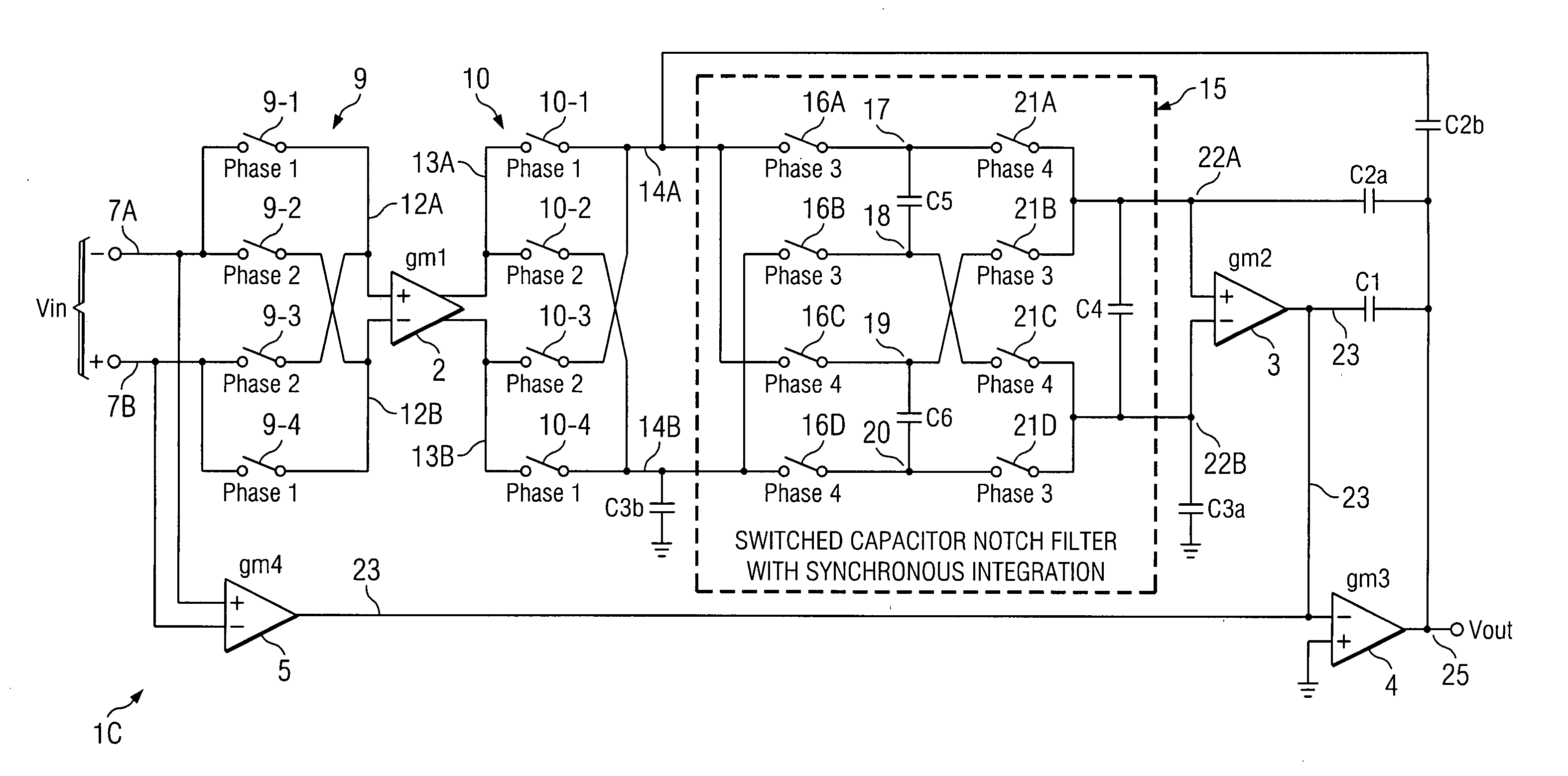
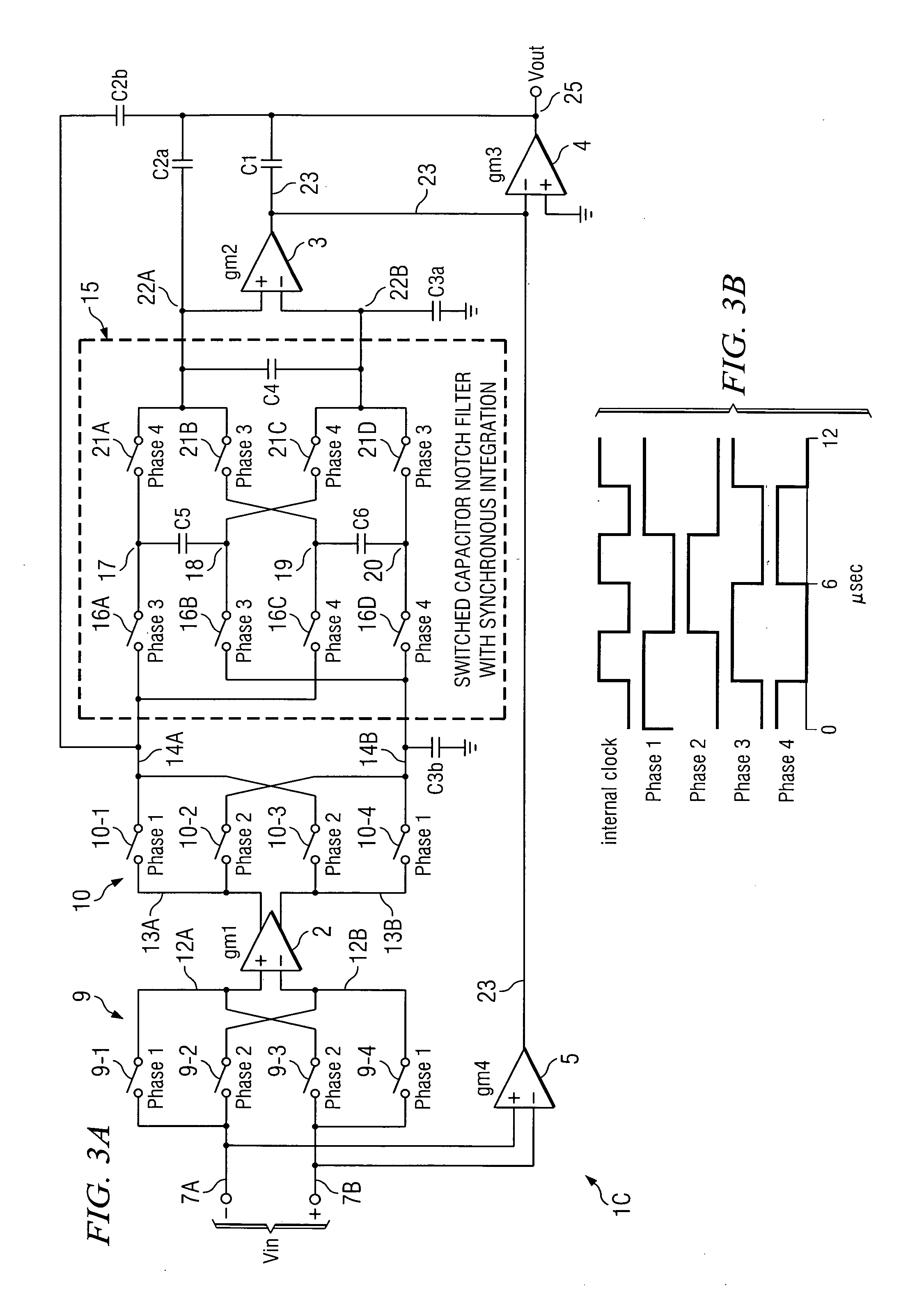
[0023] Referring to FIG. 3A, operational amplifier 1C includes (−) input conductor 7A and (+) input conductor 7B by means of which an input signal Vin is applied to input chopping circuitry 9. Chopping circuitry 9 includes switches 9-1 and 9-2 connected to (−) input conductor 7A and switches 9-3 and 9-4 connected to (+) input conductor 7B. Switches 9-1 and 9-3 are connected by conductor 12A to the (+) input of operational transconductance amplifier 2, and switches 9-2 and 9-4 are connected by conductor 12B to the (−) input of operational transconductance amplifier 2. Output conductors 13A and 13B of operational transconductance amplifier 2 are connected to output chopping circuitry 10, which includes switches 10-1 and 10-2 connected to conductor 13A and switches 10-3 and 10-4 connected to conductor 13B. Chopper switches 10-1 and 10-3 are connected to conductor 14A, and chopper switches 10-2 and 10-4 are connected to conductor 14B. The chopped output of operational transconductance a...


PUM


Abstract

A chopper-stabilized amplifier receiving an input signal includes a first operational transconductance amplifier having an input chopper and an output chopper for chopping an output signal produced by the first operational transconductance amplifier. A switched capacitor notch filter filters the chopped output signal by operating synchronously with the chopping frequency of output chopper to filter ripple voltages that otherwise would be produced by the output chopper. In one embodiment, a second operational transconductance amplifier amplifies the notch filter output. The input signal is fed forward, summed with the output of the second operational transconductance amplifier, and applied to the input of a fourth operational transconductance amplifier. Ripple noise and offset are substantially reduced.

Description

BACKGROUND OF THE INVENTION [0001] The present invention relates generally to reducing chopping noise, also referred to as ripple noise, in chopper stabilized operational amplifiers, and more particularly to using switched capacitor notch filters to reduce ripple noise. [0002] It is highly desirable that integrated circuit operational amplifiers have low offset voltage, low noise, low-offset drift, and good signal stability. Chopper stabilization and auto-zeroing are two common techniques that have been widely used to reduce amplifier offset voltage and drift. (For example, conventional chopper stabilization would typically reduce a 5 millivolt offset voltage to roughly 5 microvolts.) Modern chopper-stabilized operational amplifiers and autozero operational amplifiers have significantly reduced, or even essentially eliminated, the amount switching noise therein compared to previous designs. However, the improved design techniques used in modern chopper-stabilized operational amplifi...

Claims


Application Information

Patent Timeline
IPC IPC(8): H03F1/02
CPCH03F1/26H03F3/005H03F3/387H03F3/45968H03H2011/0488H03F2200/459H03F2203/45212H03H19/004H03F2200/261H03F1/02H03F3/45
Inventor BURT, RODNEY T.ZHANG, JOY Y.
Owner TEXAS INSTR INC
Why Eureka
Try Eureka