
Engine control device

a technology of control device and engine, which is applied in the direction of electric control, engine starter, machine/engine, etc., can solve the problems of reducing the startability of the engine, delay time (referred to as an ineffective injection time), and ineffective injection time of the injector, etc., and achieves high accuracy.

Inactive Publication Date: 2007-08-02
KOKUSAN DENKI CO LTD
View PDF3 Cites 11 Cited by
  • Summary
  • Abstract
  • Description
  • Claims
  • Application Information

AI Technical Summary

Benefits of technology

[0016]The present invention has an object to provide an engine control device that prevents a shortage in fuel injection amount at the start of an engine to improve startability of the engine, and prevents exhaust of unburned gas to improve an exhaust gas characteristic at the start of the engine.

Problems solved by technology

This causes a delay between the start of the cranking of the engine and the first fuel injection, which causes an air / fuel ratio of an air / fuel mixture supplied into a combustion chamber of the engine to reach a predetermined value with a delay, thereby failing in ignition of the fuel in first ignition (initial explosion), and reducing startability of the engine.
Poor startability of the engine increases the time for driving a rotating electric machine as a starter motor to increase power consumption of a battery, which requires a high capacity battery and is uneconomical.
The injector does not open the valve immediately after the driving voltage is supplied, but there is a delay time (referred to as an ineffective injection time) between when the driving voltage is supplied and when the valve is actually opened.
As shown in FIG. 14, the ineffective injection time of the injector changes with the magnitude of the driving voltage supplied to the injector, and is significantly increased with decreasing injector driving voltage.
Thus, as shown in FIG. 15, if the battery voltage decreases at the start of the engine to reduce the injector driving voltage, the ineffective injection time of the injector is increased to delay opening of the valve of the injector.
The delay of the opening of the valve of the injector causes a shortage in fuel injection amount even if the fuel pressure supplied to the injector is sufficiently increased, thereby often failing in initial explosion of the engine, and inevitably reducing startability of the engine.
However, at the start of the engine, changes in internal pressure of a cylinder caused by a stroke change of the engine cause a load applied to the starter motor to vary, and as indicated by the curve a in FIG. 15, the rotational speed finely changes according to crank angles, and the variation in the load causes the battery voltage to change.
As described above, the battery voltage significantly changes at the start of the engine, and thus it is actually difficult to detect the battery voltage to precisely arithmetically operate the ineffective injection time, and difficult to properly correct the ineffective injection time relative to the battery voltage to control the fuel injection amount with high accuracy.
However, when the operation permit switch is closed, the fuel pressure supplied to the injector is often insufficient.
If the fuel pressure supplied to the injector is insufficient when the operation permit switch is closed, as shown in Japanese Utility Model Laid-Open No. 60-90540, a desired amount of fuel cannot be injected even if fuel is injected when the operation permit switch is closed, and thus an air / fuel ratio of an air / fuel mixture in a cylinder in which first ignition is performed after the start goes lean, thereby failing in initial explosion, and inevitably reducing startability.
The failure in the initial explosion causes unburned gas to be exhausted to pollute the atmosphere.
Further, if the time is long between when the operation permit switch is closed and when the starter switch is closed, the fuel injected by the injector adheres to an inner surface of an intake pipe or an inner surface of a cylinder to form a liquid film, which causes a shortage of fuel that contributes to combustion, and reduces startability of the engine.
Also in this case, the failure in the ignition in the cylinder causes unburned gas to be exhausted to unpreferably pollute the atmosphere.

Method used


Image

  • Engine control device
  • Engine control device
  • Engine control device

Examples


Embodiment Construction

[0049]Now, preferred embodiments of the present invention will be described in detail with reference to the drawings.

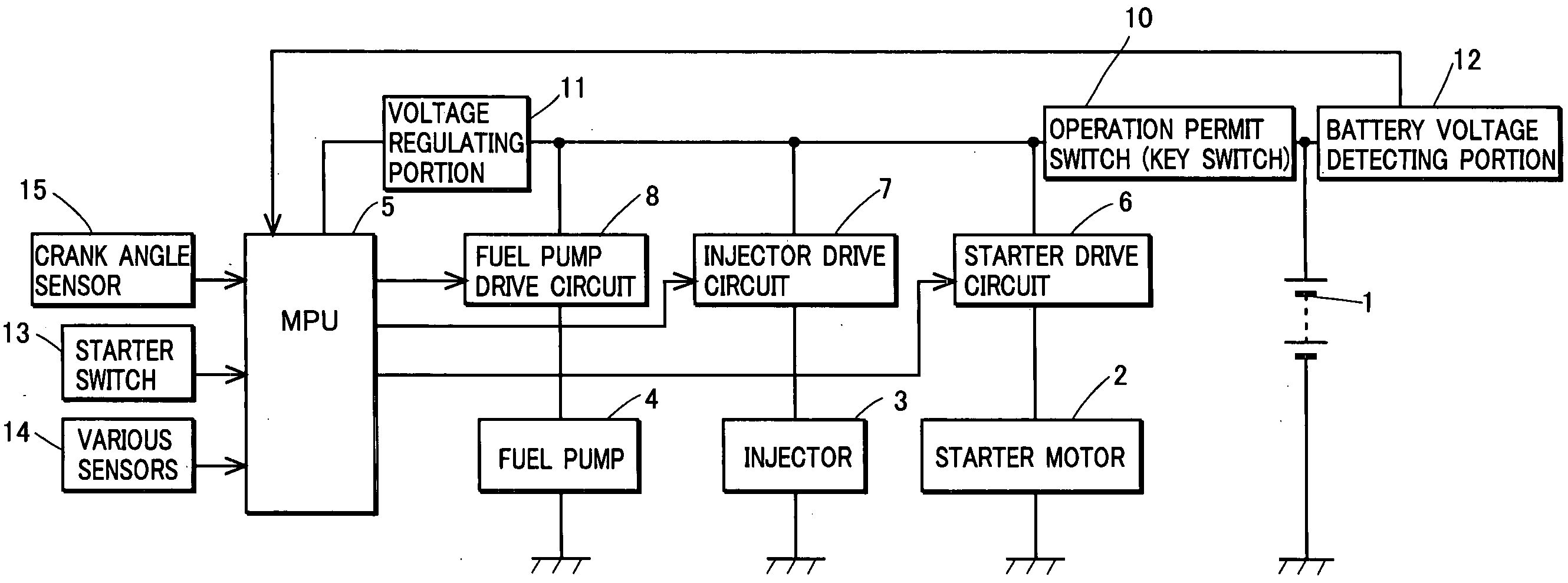
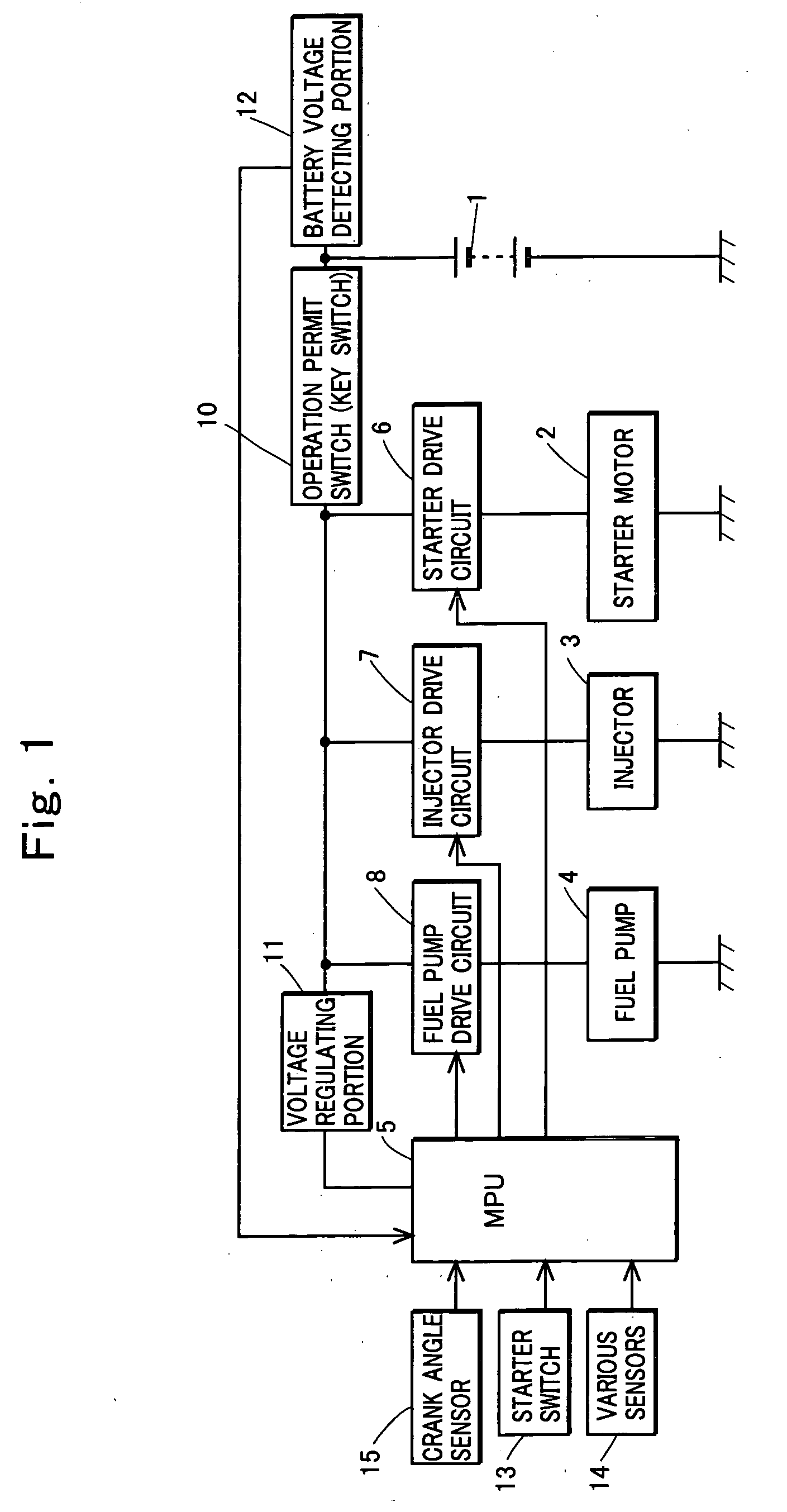
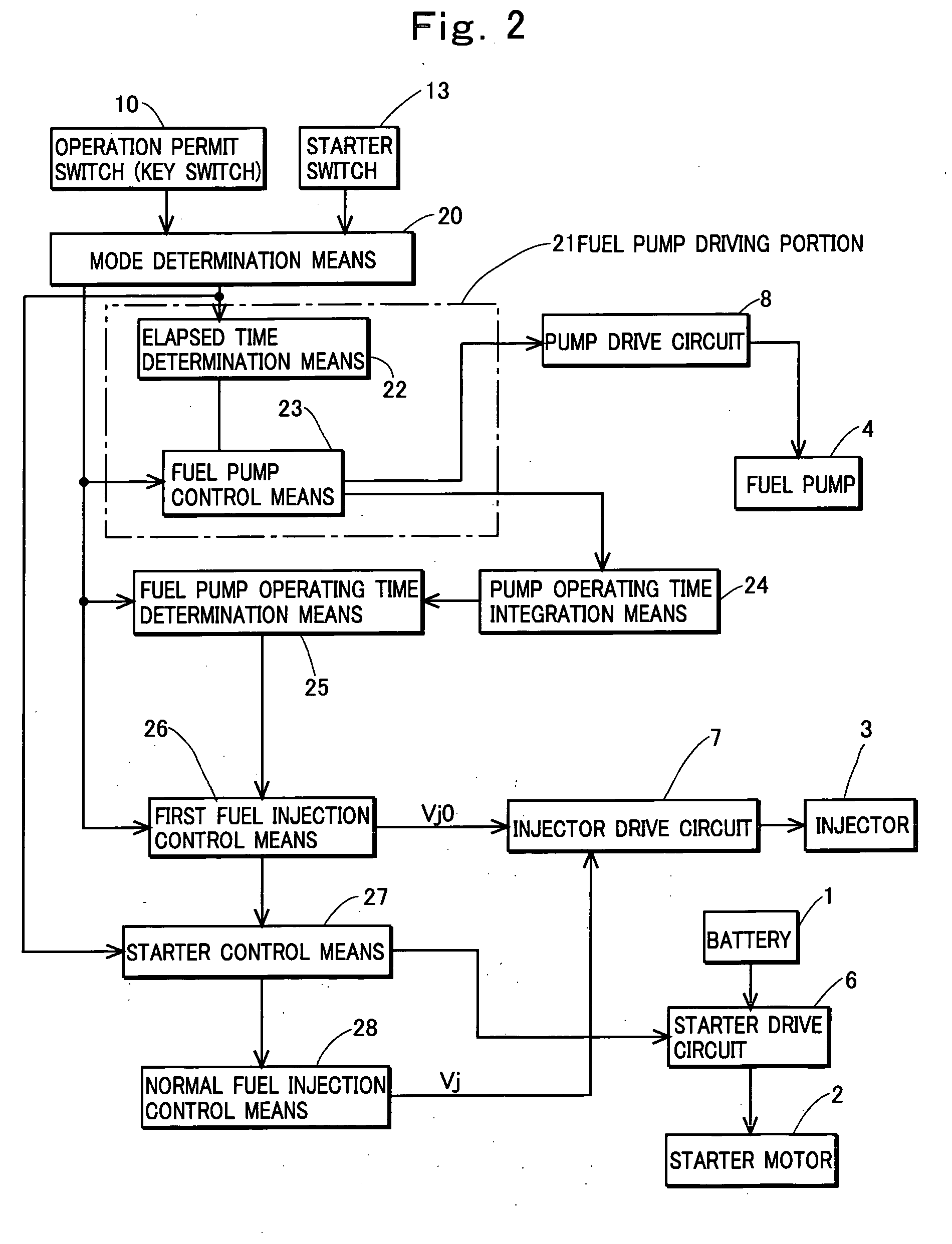
[0050]FIGS. 1 to 8 show the first embodiment of the present invention. FIG. 1 shows a construction of hardware, and FIG. 2 shows a construction of a control device including means comprised of a microprocessor. FIGS. 3 and 4 are flowcharts showing algorithms of programs executed by the microprocessor for constructing the means in FIG. 2, and FIGS. 5 to 8 are timing charts showing operations at the start of an engine in the embodiment.

[0051]The present invention may be applied to a control device that controls an engine having any number of cylinders, but for simplicity of explanation, an engine to be controlled is a single cylinder engine in the following description.

[0052]In FIG. 1, a reference numeral 1 denotes a battery, and 2 denotes a rotating electric machine that operates as an engine starting motor when an unshown engine is started. In this case, the rotating ...


PUM


Abstract

An engine control device including: a fuel pump driving portion that starts operating a fuel pump between when an operation permit switch is turned on and an operation permit command is given and when a starter switch is closed and a start command is given, and continuously operates the fuel pump after the start command is given; the first fuel injection control portion that causes an injector to perform first fuel injection at the start of an engine when both conditions are met that the start command is given and that the fuel pump is continuously operated for a set time or longer; and a rotating electric machine control portion that starts driving a rotating electric machine that operates as an engine starting motor when the first fuel injection is completed, and stops driving the rotating electric machine when the start of the engine is completed.

Description

TECHNICAL FIELD OF THE INVENTION[0001]The present invention relates to an engine control device that controls a fuel injection device, and a rotating electric machine that operates as an engine starting motor or a rotating electric machine that operates as both an engine starting motor and a battery charging generator, using a microprocessor.BACKGROUND OF THE INVENTION[0002]An engine fuel injection device is comprised of an injector, a fuel pump that supplies fuel to the injector, and a control portion that controls the injector and the fuel pump. The amount of fuel injected from the injector depends on the pressure of the fuel supplied from the fuel pump to the injector (fuel pressure) and a time for opening a valve of the injector (a valve opening time). Generally, fuel pressure supplied to the injector is controlled to be maintained constant by a pressure regulator, and thus the amount of fuel injected by the injector is controlled by the valve opening time.[0003]As described abo...

Claims


Application Information

Patent Timeline
IPC IPC(8): F02M1/00F02N17/00F02D29/02F02D41/06F02D43/00F02D45/00F02N11/04F02N11/08F02N99/00
CPCF02D41/062F02D41/266F02D41/406Y02T10/44F02N11/0848F02N19/00F02N11/0803Y02T10/40
Inventor SHIMAZAKI, MITSUYOSHIKISHIBATA, KAZUYOSHISATO, HIROYASUKINOSHITA, TOMOHIRO
Owner KOKUSAN DENKI CO LTD
Learn More