Single drive and source for adjacently clamping and resistance welding

Inactive Publication Date: 2007-08-02
GM GLOBAL TECH OPERATIONS LLC
View PDF0 Cites 27 Cited by
  • Summary
  • Abstract
  • Description
  • Claims
  • Application Information

AI Technical Summary

Benefits of technology

[0012] A second aspect of the present invention concerns a method of clamping and welding a plurality of workpieces in a predetermined assembly configuration and reducing assembly cell congestion, wherein at least one datum location for clamping the workpieces is predetermined, so as to minimize deformation during clamping and welding. The method further includes the steps of fixing the workpieces in the assembly configuration, and securing a clamping and welding system having a single drive mechanism in relation to the workpieces. The workpieces at the datum location are then engaged by actuating the drive mechanism of the system, so as to clamp and retain the workpieces in the assembly configuration. Finally, an electric current is applied through and pressure is applied to the workpieces at a second location substantially adjacent the first location also by the actuation of the drive mechanism.
[0013] It will be understood an

Problems solved by technology

Due to equipment size and configuration (e.g., robotic bulk), however, the electrodes are typically unable to produce these welds near or substantially adjacent the datum location, and must therefore engage the workpieces at locations spaced a minimum distance from the datum locations.
Applying compressive welding forces at these non-datum locations results in workpiece deformation that reduces dimensional accuracy.
However, the longer arms have resulted in an increase in the total size of the gun unit, as the required input force has correspondingly increased.
These multi-robotic systems further present vario

Method used


Image

  • Single drive and source for adjacently clamping and resistance welding
  • Single drive and source for adjacently clamping and resistance welding
  • Single drive and source for adjacently clamping and resistance welding

Examples


Embodiment Construction

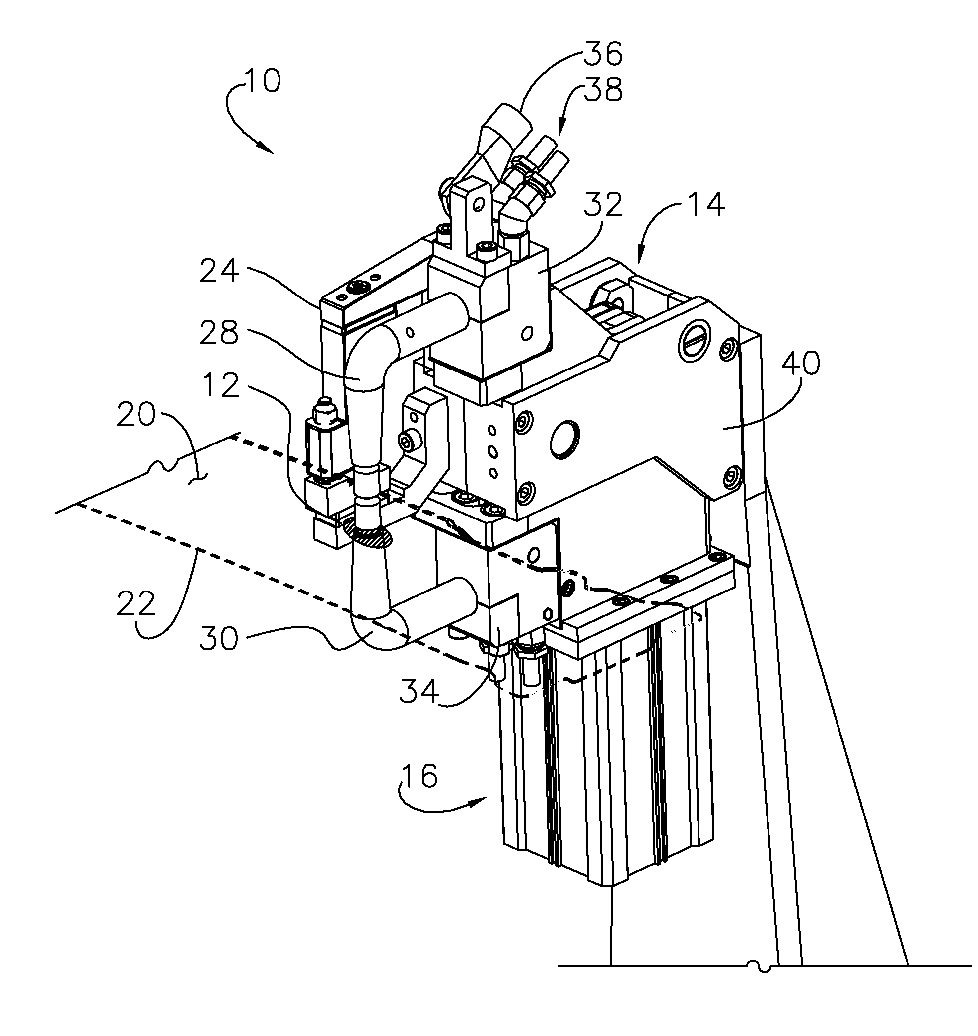
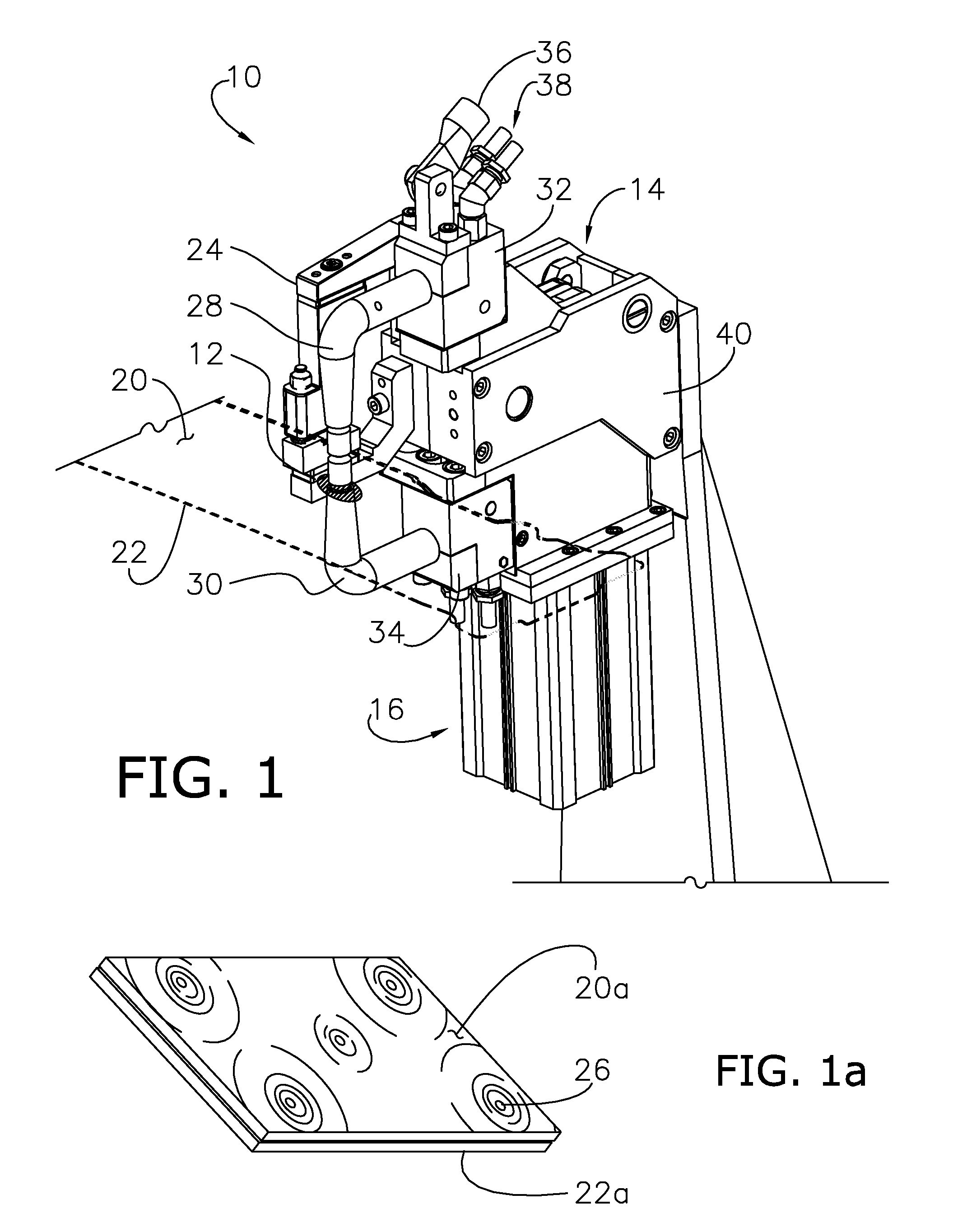
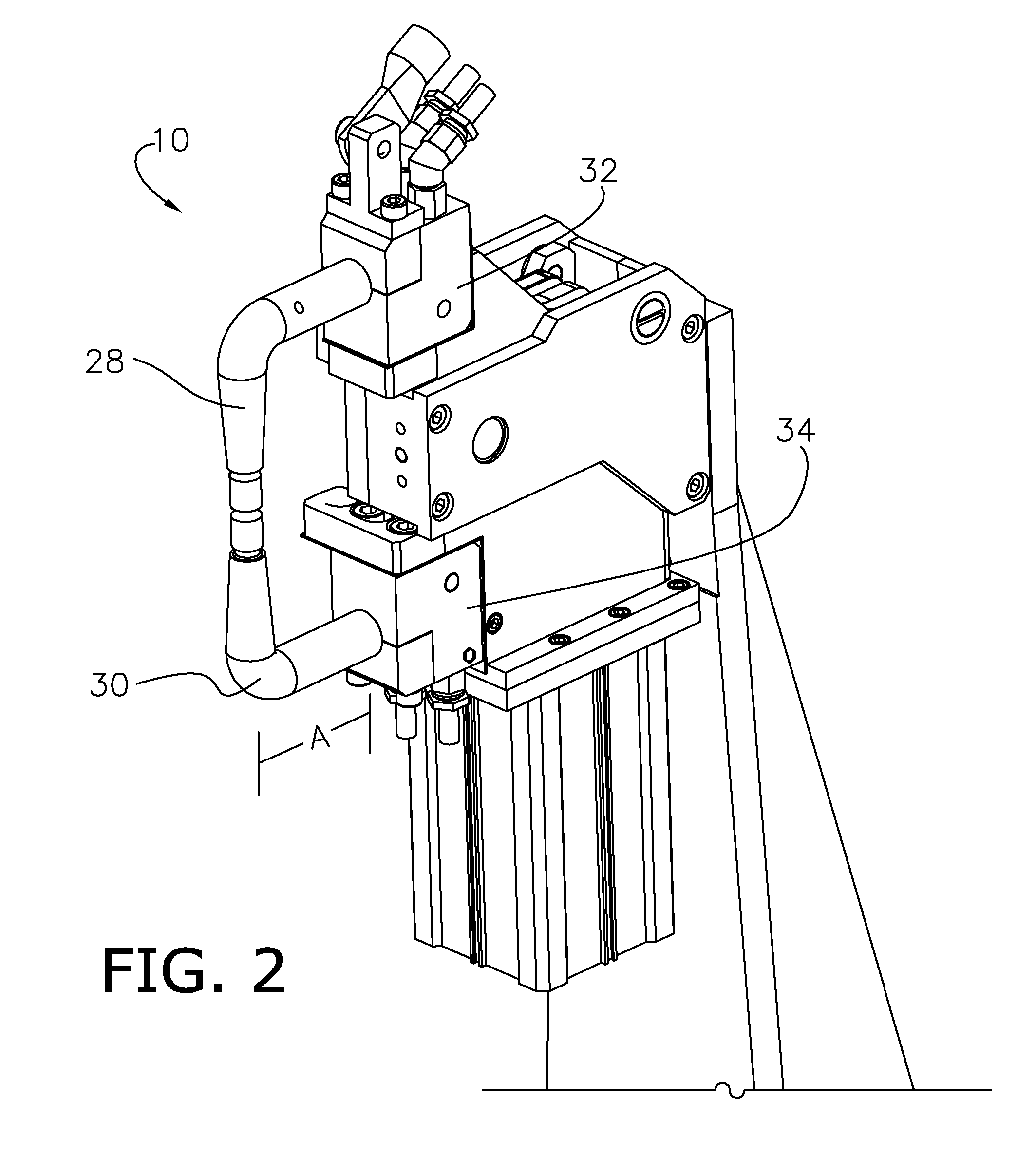
[0033] As best shown in FIG. 1, the present invention concerns an improved resistance welding system 10 for clamping and welding a plurality of workpieces, such as the component parts of a body-panel or support roof assembly of an automobile, to produce a spot or seam weld 12. The inventive system 10 includes a single drive mechanism 14 and a single combined clamping and welding force generating source 16. The system 10 is intended for use within an assembly station, wherein the workpieces are first placed upon station fixture 18 (FIG. 6) by a human or robotic operator (not shown). The preferred system 10 is robotically maneuverable into position along multi-axes, configured to receive sensory input, and is programmably controlled. Although described and illustrated herein with respect to spot welding, it is appreciated that the inventive aspects of the system 10 may be utilized with other compressive joining means, such as weldbonding, riveting, rivetbonding, clinching, clinchbondi...


PUM

PropertyMeasurementUnit
Pressureaaaaaaaaaa
Angleaaaaaaaaaa
Angleaaaaaaaaaa

Abstract

A resistance spot welding system (10) for sequentially clamping a plurality of workpieces (20,22) at predetermined locations and welding the workpieces (20,22) substantially adjacent the locations, including a clamping element (24) able to be locked in a workpiece engaged position, at least one set of equalizing welding electrodes (28,30) for oppositely engaging the workpieces (20,22) so as to produce the weld (12) without deformation, a singular drive mechanism (14) including a cam coupled to the clamping element (24) and electrodes (28,30), and a singular source (16) for actuating the mechanism (14) and generating the welding and clamping forces.

Description

CROSS-REFERENCES TO RELATED APPLICATIONS [0001] This U.S. Non-Provisional patent application is a continuation-in-part and claims the benefit of pending U.S. Non-Provisional Ser. No. 11 / 178,171 filed on Jul. 8, 2005, entitled SYSTEM AND METHOD FOR CLAMPING AND RESISTANCE WELDING (hereinafter the 171 application), incorporated by reference herein.BACKGROUND OF THE INVENTION [0002] 1. Technical Field [0003] The present invention relates to resistance spot welding systems and methods and more particularly to an improved resistance spot welding system having a single drive and source for clamping a plurality of workpieces at a first location and welding the workpieces substantially adjacent the first location. [0004] 2. Discussion of Prior Art [0005] Resistance spot welding systems are used in various industrial applications, including automotive vehicle body construction. These systems function to apply pressure to and transmit an electric current through a plurality of adjacently secu...

Claims


Application Information

Patent Timeline
IPC IPC(8): B23K11/10
CPCB23K11/3081B23K11/115B23K11/31B23K11/314
Inventor CHRISTENSEN, TOMMYWANG, PEI-CHUNGDEAL, SCOTT E.LILJA, THOMASBOGREN, PETER
Owner GM GLOBAL TECH OPERATIONS LLC
Why Eureka
Try Eureka