Beverage dispensing system pressurized release liquid USPA2

a technology of pressurized liquid and beverage containers, which is applied in the field of beverage containers, can solve the problems of unintentional spillage, inconvenient use, and fluid inside the container is prone to surrounding contamination, and achieves the effects of convenient packaging, less physical effort, and increased marketability of products

Inactive Publication Date: 2007-08-02
SIRI ADAM
View PDF6 Cites 9 Cited by
  • Summary
  • Abstract
  • Description
  • Claims
  • Application Information

AI Technical Summary

Benefits of technology

[0025]From the above it is clear that the straws and container for dispensing the liquid in the prior art have a limited scope. The present invention provides a comprehensive solution by addressing all of the disadvantages of previous liquid dispensing systems. The pressurized liquid dispensing system is capable of maintaining the gas pressure inside the container. The dispensing system prevents spilling of the liquid in all conditions in practice, could be cleaned and refilled, with ease of packaging and pleasing appearance. One can drink the liquid inside the container with less physical effort, an injured person can drink by holding in any orientation. It can be used for hot drinks and beverages as well. Further it could be used as a drinking utensil and a spray bottle. The product is an appeal to the thirst for novelty thereby increasing the marketability of the product.

Problems solved by technology

Simple straight rod like straws were used initially but they were very inconvenient to use.
There are many problems associated with the simple straw as well as the straws with bellows.
The opening provided on the container for inserting the straw in the container is greater than the straw diameter, so the fluid inside the container is prone to surrounding contamination at the same time there is a fear of unintentional spillage.
The process of manufacturing these components is very complex.
Mounting the straw is not so easy, the handling and packaging of the container is not friendly and it does not look good in its appearance.
Further the main problem with this tube is that the liquid inside the container may gush out of the beverage container through the tube in the conditions of excessive external or internal pressure on the beverage container.
The problem of withstanding high pressure remains unresolved.
It leads to dripping of the liquid inside the container when the container is inverted.
The spouting of liquid is possible due to excessive outside pressure or when the user is riding or driving a vehicle.
But this is not desirable and fails when the user has to apply a sucking force beyond this capacity.
This would be unmanageable.
However the drawback of these containers is that once the seal is opened it should be consumed within a limited duration of time before the carbon dioxide is released, otherwise it goes flat and tasteless.
These containers are made of aluminum and cannot be reused or refilled.
The amount of force needed in a spring to hold down the pivot against the contents would make it nearly impossible for an average person to open the valve.
If the valve closing means as embodied and described were strengthened it would have a direct affect on the strength needed for opening valves opening means making it more difficult to open, and the amount of strength that is needed to make the closing means stay closed under the relevant pressure, if the strength were added, would make the opening means very difficult if not impossible by an ordinary person to open.

Method used


Image

  • Beverage dispensing system pressurized release liquid USPA2
  • Beverage dispensing system pressurized release liquid USPA2
  • Beverage dispensing system pressurized release liquid USPA2

Examples


Embodiment Construction

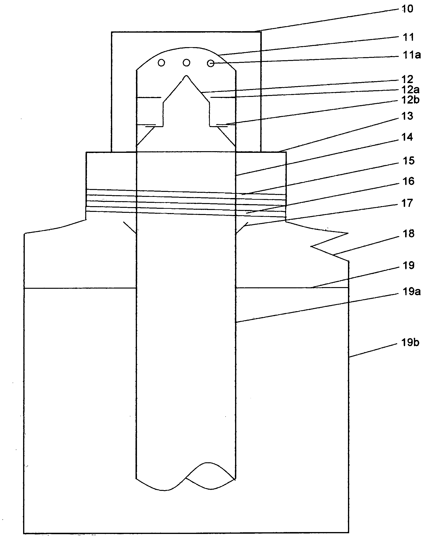
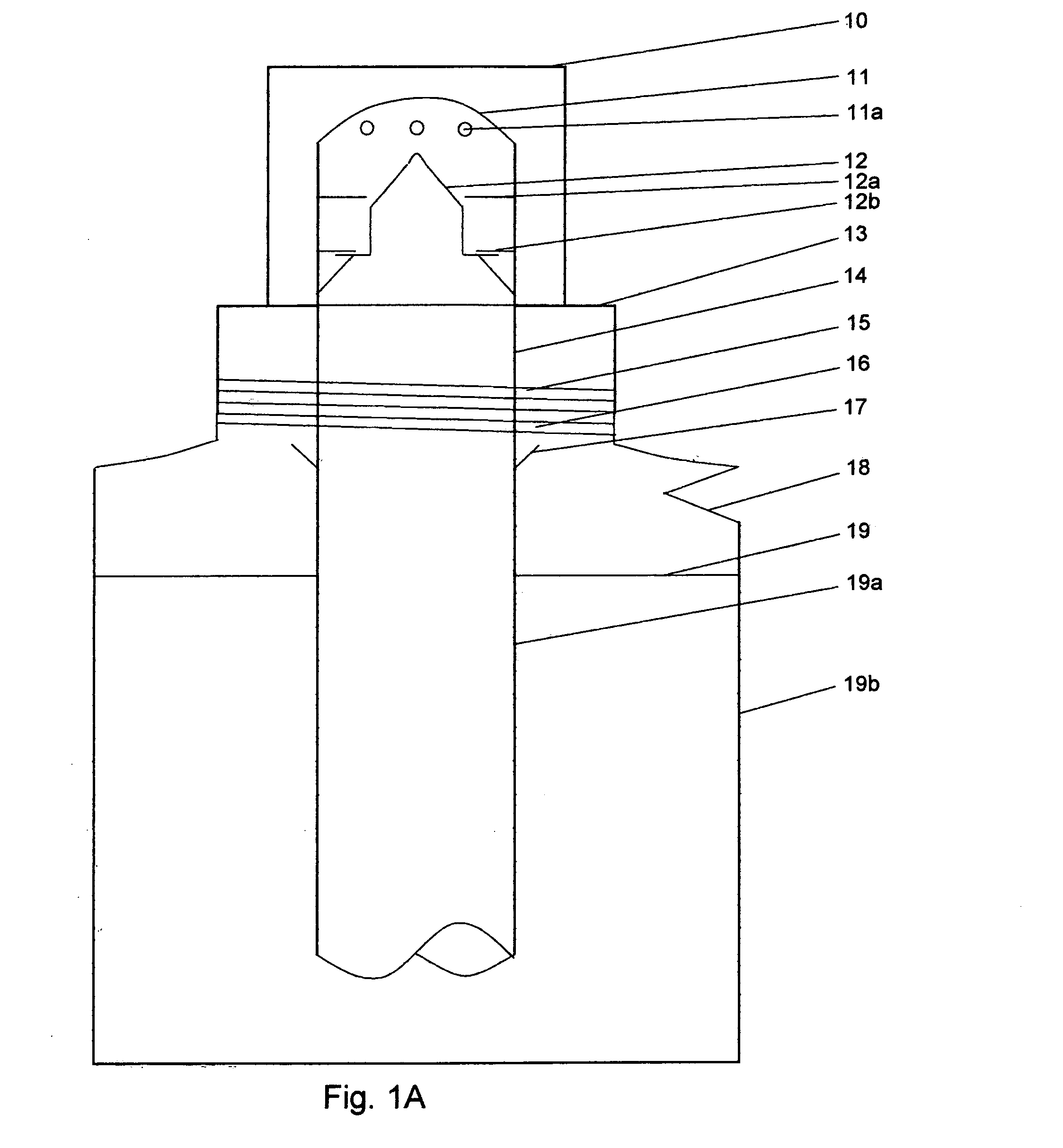
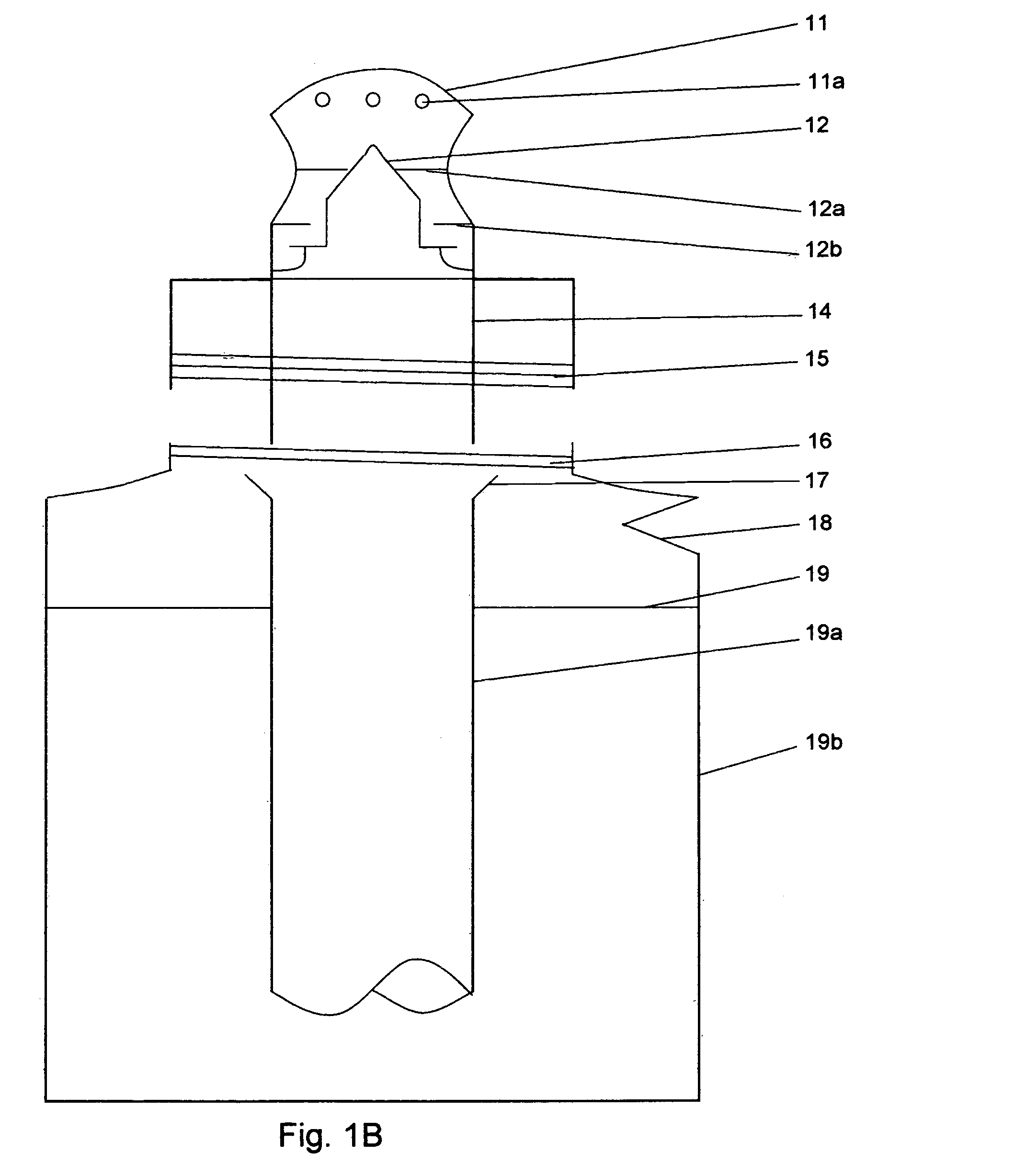
[0224]FIG. 1A shows a front view of a preferred embodiment of the present invention with a nipple cap, the cap screwed on to the container and the valve in the closed position. FIG. 1B shows a front view of the embodiment shown in FIG. 1A with the nipple cap off, the cap screwed off the container and the valve in the open position.

[0225]These figures illustrate a new means of contents regulated in a beverage container and the embodiments to follow will show, replacements of means or parts depicted in this first embodiment and will show add on means or parts that may be added to this first embodiment and certain means or parts depicted in this first embodiment may be removed.

[0226]FIG. 1A shows a cover 10 which is placed on top of the top part of cap tube 14 (nipple) and is removable. The cover 10 protects the nipple from dirt. The top part of the cap tube 14 (nipple) projects thru the top horizontal wall of the cap 13 and the cap tubes 14 walls outer perimeter is attached hermetical...


PUM


Abstract

A liquid beverage dispensing system having a specialized sealed container and a tube which extends from a top of the container and terminates just before the floor of the container. The tube has a one way valve that allows liquid to come up and out of the container when the valve is opened. Before the valve is opened the liquid may be a carbonated liquid under pressure. Then the valve opens upon the user's action, such as, sucking or squeezing the nipple. When the valve is opened the pressure inside of the container exerted by rising or trapped air bubbles exerts a downward force on the liquid below. The downward force thereby pushes the liquid below into and up the tube and into the user's mouth. The one way valve having unique form characteristics to permit this operation and permit other operations.

Description

CROSS REFERENCE TO RELATED MATERIAL[0001]This application claims the benefit of provisional patent applications;Serial Number60 / 649,347FiledFeb. 02, 2005Serial Number60 / 650,484FiledFeb. 07, 2005Serial Number60 / 651,924FiledFeb. 10, 2005Serial Number60 / 655,631FiledFeb. 23, 2005Serial Number60 / 688,015FiledJun. 07, 2005Serial Number60 / 736,994FiledNov. 15, 2005Serial Number11 / 320,458FiledDec. 28, 2005Serial NumberPCT / US2006 / 002706FiledJan. 25, 2006Serial Number60 / 763,299FiledJan. 30, 2006[0002]By the present inventor.BACKGROUND ART[0003]U.S. Patent Documents5,186,34702 / 1993 Freeman et al.220 / 2545,482,20201 / 1996 Wen229 / 103.16,290,090 B109 / 2001 Essebaggers220 / 7106,427,928 B108 / 2002 Hirota et al.239 / 336,360,912 B103 / 2002 Lee220 / 7056,745,949 B206 / 2004 Lee239 / 33[0004]1. Field of the Invention[0005]The field of the present invention is that of beverage containers. The closest related art are of no spill beverage containers, stoppage of carbonation loss, and the like. There are no prior art pro...

Claims


Application Information

Patent Timeline
Patent Type & Authority Applications(United States)
IPC IPC(8): A47G19/22
CPCB65D47/20B65D83/752B65D83/32B65D81/36
Inventor SIRI, ADAM
Owner SIRI ADAM
Why Eureka
Try Eureka