Electric double layer capacitor

Inactive Publication Date: 2007-08-02
SANYO ELECTRIC CO LTD
View PDF12 Cites 21 Cited by
  • Summary
  • Abstract
  • Description
  • Claims
  • Application Information

AI Technical Summary

Benefits of technology

[0013]According to the above aspect of the electric double layer capacitor of the present invention, by fitting the sealing plate inside the concave-shaped container, the positioning between the sealing plate and the container becomes easy, and a displacement of the sealing plate in the horizontal direction can be reduced. Therefore, the decline of the yield can be prevented.
[0014]By making the container of ceramics, a shape deformation of the container due to heat can be reduced, when executing the sealing by heating such as welding. Thus, a decline of the sealing reliability can be reduced.
[0015]By making the sealing plate of a metal, the sealing becomes easy because the heat is easily transmitted when executing the sealing by heating such as welding. Additionally, it becomes possible to pass a current by contacting a welding electrode to the sealing plate, when welding under a principle of resistance welding, such as a seam welding. At this point,

Problems solved by technology

Therefore, there was a problem that a cost of parts and manufacturing are expensive.
Moreover, when the can container is the coin type, there was a problem that a dead space tends to exi

Method used


Image

  • Electric double layer capacitor
  • Electric double layer capacitor
  • Electric double layer capacitor

Examples


first example

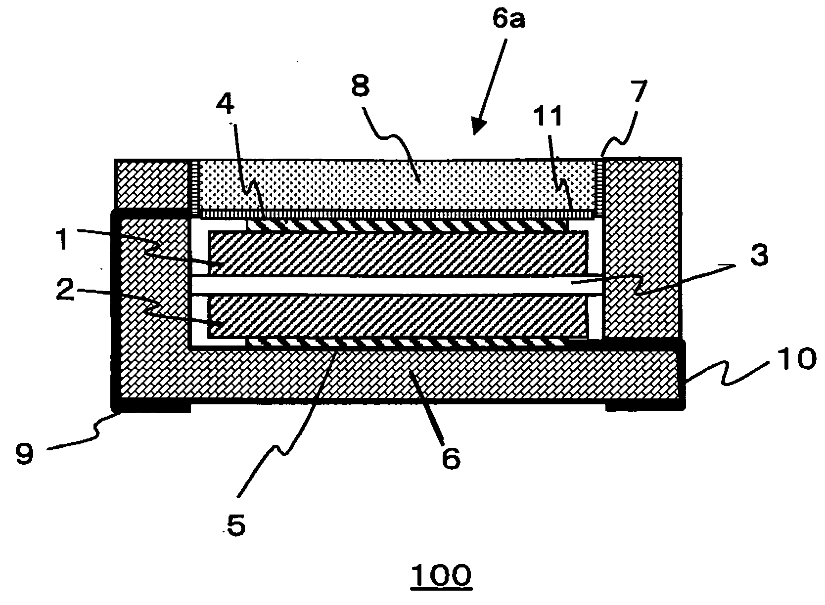
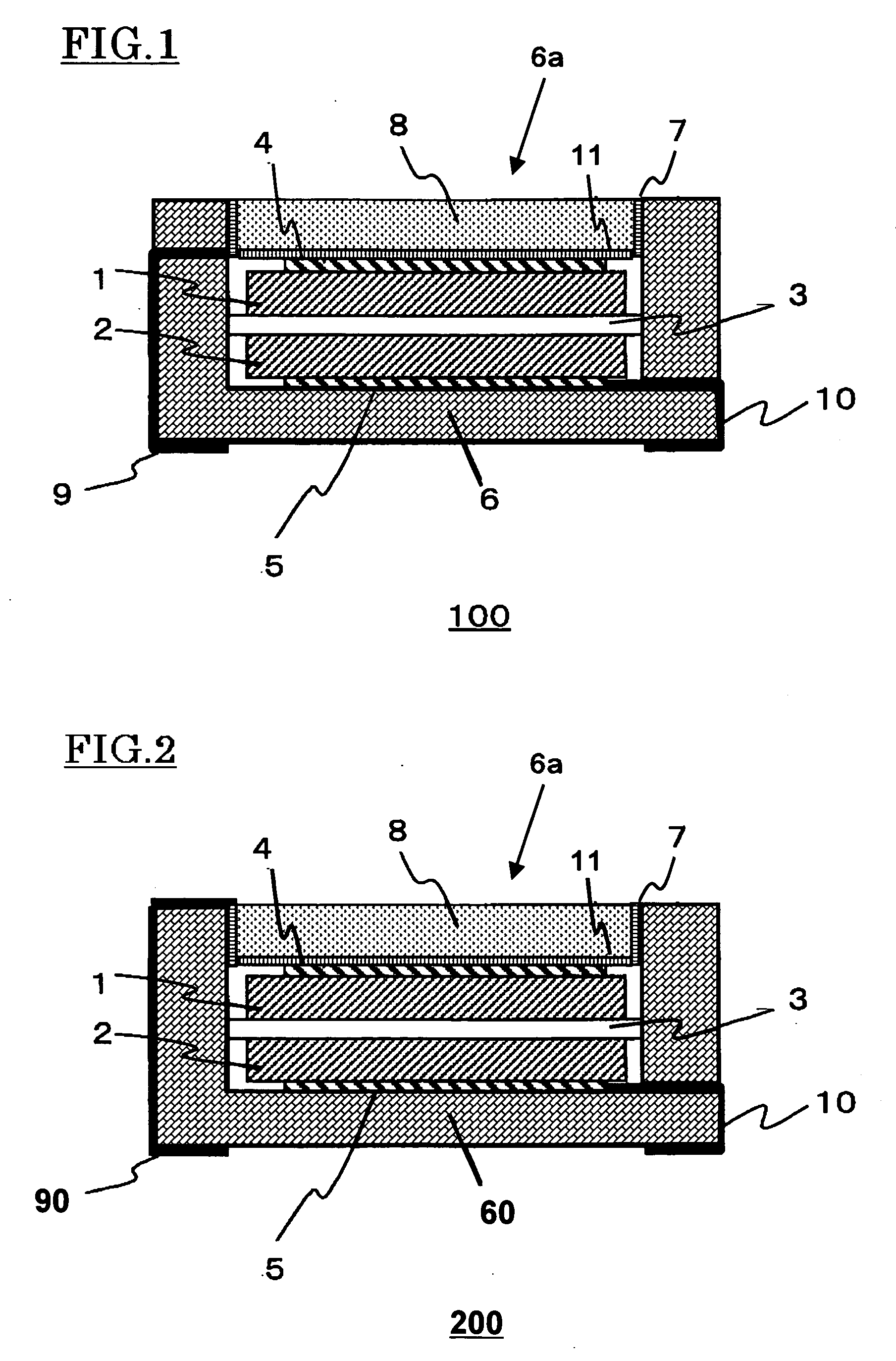
[0027]FIG. 1 shows the structure of the electric double layer capacitor 100 of the first example. Here, 1 is a first electrode, 2 is a second electrode, 3 is a separator, 4 is a first current collector, 5 is a second current collector, 6 is a concave-shaped container, 6a is an containing space, 7 is a metal layer, 8 is a sealing plate, 9 is a first external connecting terminal, 10 is a second external connecting terminal, and 11 is a metal layer.

[0028]The concave-shaped container 6 is a frame object made from alumina, having a square shaped undersurface of 5 mm on each side, and height of 1.6 mm. On the upper surface side of the container 6, a concave shaped containing space 6a having 3.6 mm on each side square and depth of 1.4 mm is formed. On the bottom part of the unit 6a, the current collector 5, where gold is coated on tungsten, is formed.

[0029]On an undersurface of a bottom wall portion and on an external surface of the side wall portion of the concave-shaped container 6, the ...

second example

[0037]As shown in FIG. 2, in an electric double layer capacitor 200 of the second example, a first external connecting terminal 90 is formed along the external surface of the concave-shaped container 60 from the bottom end to the upper end, and the first external connecting terminal 90 is extended to the internal surface of the concave-shaped container 60 along an edge part of the opening part. This is an alternative to the first external connecting terminal 9 of the capacitor 100 in the first example which penetrated through the side wall portion of the concave-shaped container 6. A metal layer 7, which is on an internal surface of the containing space 6a, is formed so that it can cover the first external connecting terminal 90. Except the above, the capacitor 200 of the second example has same configurations as the capacitor 100, and the same numbers are attached in the figure for the same configurations.

[0038]According to the present example, by having a structure fitting the sea...

third example

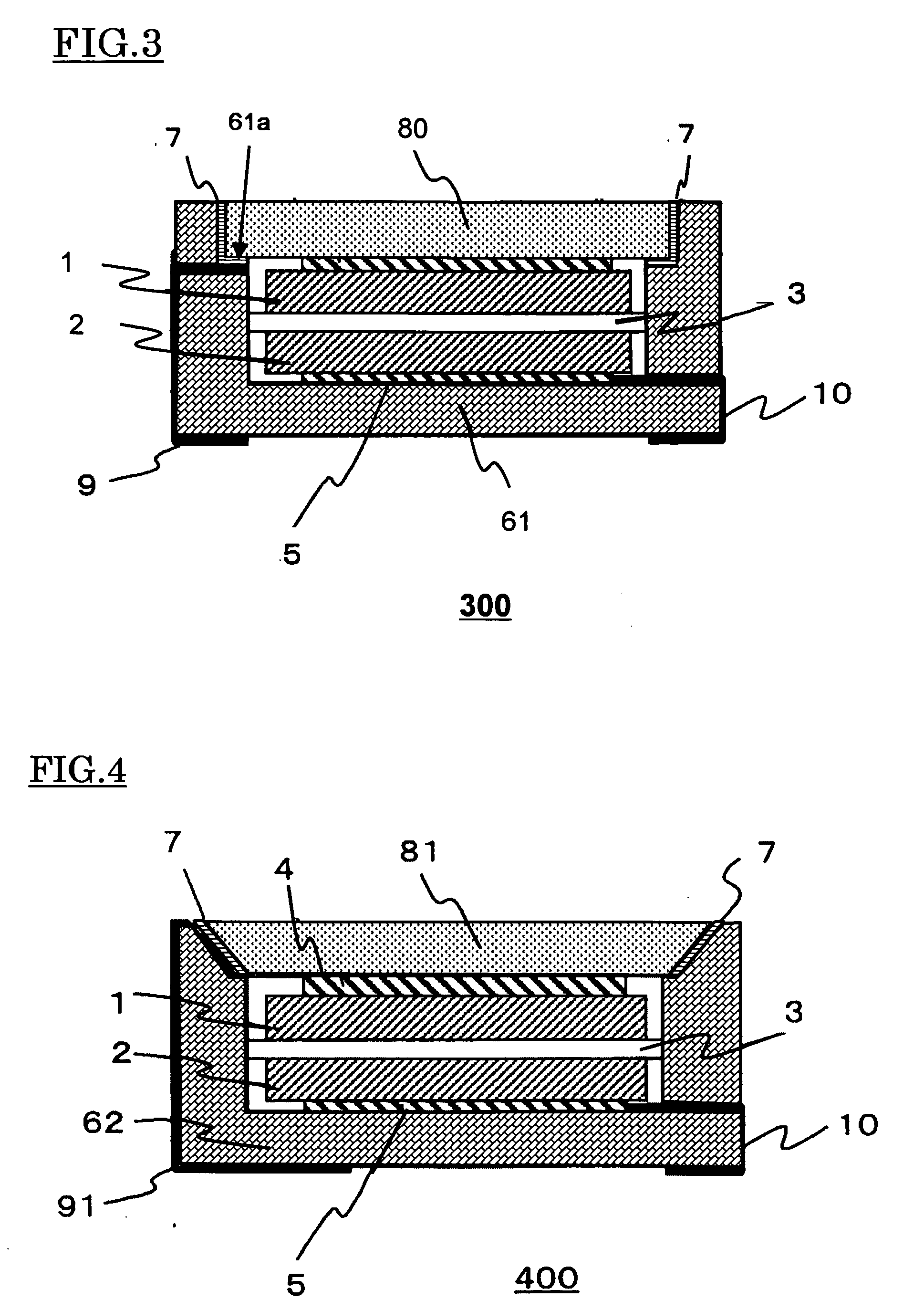
[0039]As shown in FIG. 3, in the electric double layer capacitor 300 of the third example, a level difference part 61a forms an internal surface of the concave-shaped container 61. In other words, the containing space of the container 61 has a lower containing space having a square shaped surface of 3.6 mm on each side and 1.1 mm depth and an upper containing space having a square shaped surface of 4 mm on each side and 0.3 mm depth. When viewing the part 61a from the upper surface side, the part 61a looks like a square strip shaped object, where the width of the strip is 0.2 mm. The external connecting terminal 9, which penetrates through the side wall of the container 61, is formed extending to the part 61a. The external connecting terminal 9 may be extended to an inner edge part of the level difference part 61a. The metal layer 7 is formed on an area contacting with a sealing plate 80 when sealing to the internal surface of the container 61 and on the part 61a. The metal layer 7 ...


PUM


Abstract

An electric double layer capacitor comprises an electrode, a current collector, an electrolyte, a separator, a concave-shaped container for accommodating them, and a sealing plate for sealing an opening part of the container, wherein the sealing plate is fitted inside the container.

Description

[0001]This application is based upon and claims the benefit of priority from prior Japanese Patent Application No. 2006-023840, filed on Jan. 31, 2006 and prior Japanese Patent Application No. 2006-219108, filed on Aug. 11, 2006; the entire contents of which are incorporated herein by reference.BACKGROUND OF THE INVENTION[0002]1. Field of the Invention[0003]The present invention relates to an electric double layer capacitor.[0004]2. Description of the Related Art[0005]Conventionally, an electric double layer capacitor is known as a device, besides a chemical cell, which accumulates electrical energy. In the electric double layer capacitor, electrodes, which are made by an electrode material having a large specific surface area such as activated carbon, and an electrolyte, are used. Those electrodes are formed to face each other, and the electrolyte forms a dielectric layer called a Helmholtz layer. Since the electric double layer capacitor accumulates the electrical energy only by m...

Claims


Application Information

Patent Timeline
IPC IPC(8): H01G9/00H01G9/08H01G9/10H01G11/00H01G11/22H01G11/24H01G11/38H01G11/42H01G11/74H01G11/78H01G11/80H01G11/82H01G11/84H01G11/86
CPCH01G9/016H01G9/06H01G9/10Y02E60/13H01G11/74H01G11/80H01G9/155
Inventor UMEMOTO, TAKASHINAKAHARA, YASUONONOUE, HIROSHINEMOTO, MASAAKI
Owner SANYO ELECTRIC CO LTD
Why Eureka
Try Eureka