Multiple discharge ignition control apparatus and method for internal combustion engines

Inactive Publication Date: 2007-08-09
DENSO CORP
View PDF6 Cites 66 Cited by
  • Summary
  • Abstract
  • Description
  • Claims
  • Application Information

AI Technical Summary

Benefits of technology

[0008]It is therefore an object of the invention to provide multiple discharge ignition control apparatus and method for internal co

Problems solved by technology

In such a case, the flow velocity of gas around the spark plug is increased, and this increases a voltage required to hold ignition discharge.
In such an environment, a required secondary current cannot be ensured.
In addition, since the flow velocity of gas in proximity to a spark plug is high in such engines, ignition discharge can vanish during multiple discharge.
However,

Method used


Image

  • Multiple discharge ignition control apparatus and method for internal combustion engines
  • Multiple discharge ignition control apparatus and method for internal combustion engines
  • Multiple discharge ignition control apparatus and method for internal combustion engines

Examples


first embodiment

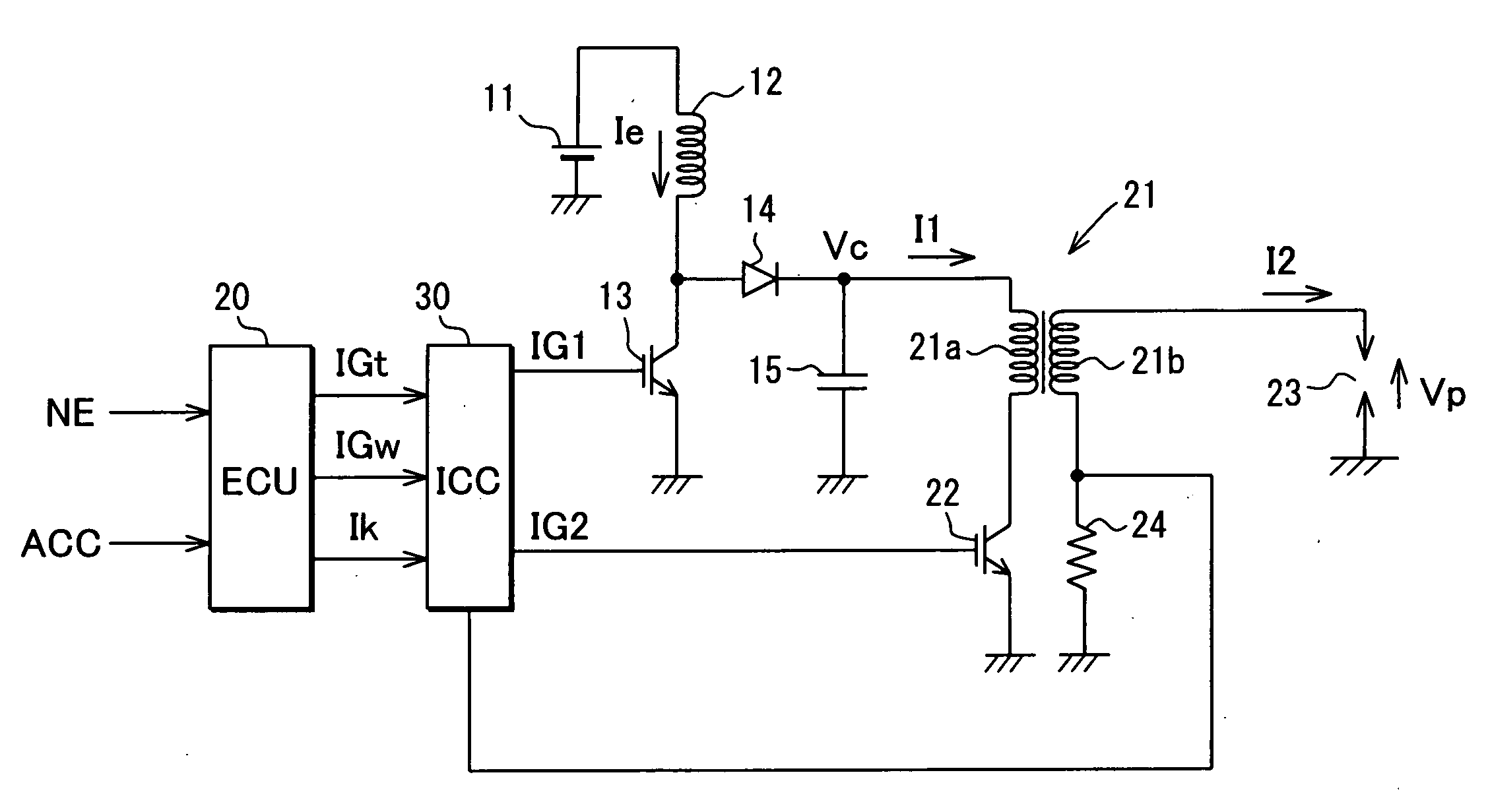
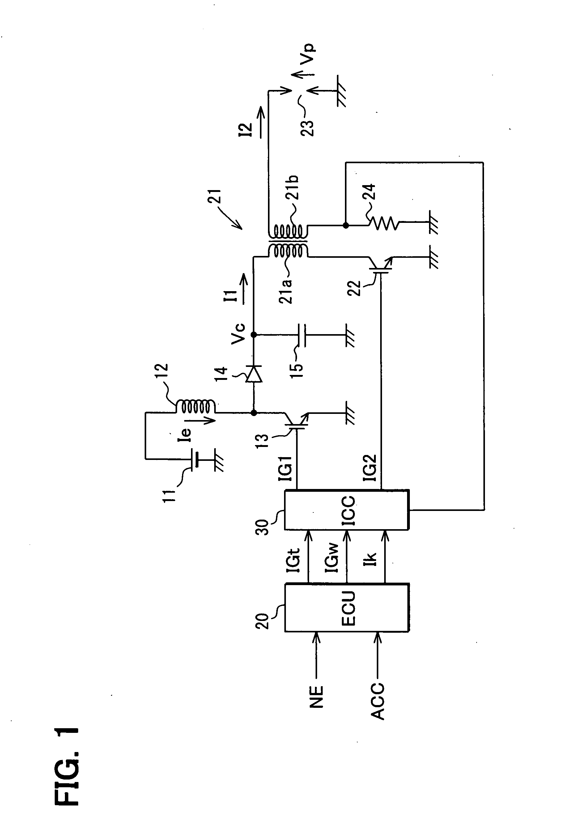
[0029]Referring first to FIG. 1, a battery 11 as a direct-current power source is connected in series with an energy storage coil 12 and a first IGBT 13. When the IGBT 13 is ON, electrical energy is stored in the energy storage coil 12. Between the energy storage coil 12 and the IGBT 13, a capacitor 15 is connected for capacitive discharge through a diode 14. This capacitor 15 is charged with the electrical energy stored in the energy storage coil 12.

[0030]An ignition coil 21 provided for each cylinder of the engine is constructed with a primary coil 21a and a secondary coil 21b. One end of each primary coil 21a is connected with the capacitor 15, and the other end is connected with a second IGBT 22. As a result of this IGBT 22 being turned on / off, the electrical energy stored in the energy storage coil 12 and the capacitor 15 is released, and a primary current I1 is supplied through the primary coil 21a thus energizing the primary coil 21a. One end of each secondary coil 21b is con...

second embodiment

[0048]A second embodiment is constructed to meet ultra-lean burn engine, in which an air-fuel ratio is significantly made lean. Therefore the plug voltage required for effecting ignition discharge is 2 to 5 kV or so and the discharge holding current required for the same is 50 to 100 mA or so. The second embodiment has a DC / DC converter as power supply means for boosting and outputting battery voltage.

[0049]As illustrated in FIG. 7, the battery 11 is connected with a DC / DC converter 41 with an output voltage of Vdc (several tens to a hundred of volts or so). At the same time, the DC / DC converter 41 is connected in series with the primary coil 21a through a diode 42 for reverse-flow prevention. This DC / DC converter 41 may be a conventional booster circuit constructed with an inductor, a transistor, a diode and a capacitor. With this construction, when IGBT 22 is turned on, the output voltage Vdc of the DC / DC converter 41 is applied to the primary coil 21a, and electrical energy is su...

third embodiment

[0055]In a third embodiment shown in FIG. 9A, a DC / DC converter 51 is provided as a power supply means for boosting and outputting battery voltage. Further, an H-bridge circuit is constructed with transistors 52, 53 and IGBTs 22, 54 to supply a current from the DC / DC converter 51 to the primary coil 21a of the ignition coil 21 both in the forward direction and in the reverse direction. By supplying the current through the primary coil 21a both in the forward direction and in the reverse direction by this H-bridge circuit, electrical energy required for ignition discharge is supplied.

[0056]Specifically, the battery 11 is connected with the DC / DC converter 51 with the output voltage Vdc (several tens to a hundred of volts or so). The primary coil 21a is connected to the DC / DC converter 51 through either transistor 52 or 53 and is grounded through either IGBT 22 or 54. With this construction, when the transistor 52 and the IGBT 22 are turned on with the transistor 53 and the IGBT 54 be...


PUM


Abstract

In a multiple discharge ignition control apparatus, a battery, an energy storage coil and a first IGBT are connected in series. Further, the energy storage coil, a diode, a primary coil and a second IGBT are connected in series. The energy storage coil is connected with a capacitor through the diode, and a secondary coil is connected with a spark plug and a resistor for current detection. An ignition control circuit switches the IGBTs between ON and OFF each time the secondary current detected by the resistor reaches a positive or negative discharge holding current in multiple discharge operation. A booster circuit is provided in addition to the energy storage coil and its output is feedback-controlled.

Description

CROSS REFERENCE TO RELATED APPLICATION[0001]This application relates to and incorporates herein by reference Japanese Patent Applications No. 2006-30532 filed on Feb. 8, 2006 and No. 2006-292549 filed on Oct. 27, 2006.FIELD OF THE INVENTION[0002]The present invention relates to multiple discharge ignition control apparatus and method for internal combustion engines and in particular to multiple discharge ignition control apparatus and method for internal combustion engines that effects ignition discharge at a spark plug multiple times in one combustion stroke of each cylinder.BACKGROUND OF THE INVENTION[0003]In a spark ignition internal combustion engine, ignition discharge is effected at a spark plug by an ignition device including an ignition coil and the like, and fuel, guided into a combustion chamber, is burned by this ignition discharge. To make the combustion condition more desirable, multiple discharge is proposed to effect ignition discharges at a spark plug more than once ...

Claims


Application Information

Patent Timeline
IPC IPC(8): F02P15/08F02P3/02F02P3/05
CPCF02P3/0552F02P15/08F02P5/1512
Inventor TORIYAMA, MAKOTOYAMAUCHI, YUKI
Owner DENSO CORP
Why Eureka
Try Eureka