
System and method for preventing blow-by of liquefied gases

a technology of liquefied gas and system, applied in the field of process control, can solve the problems of large, dangerous cloud of boiling white ln2 “smoke” and “blow-by” of liquefied gas, and achieve the effect of preventing the blow-by of ln2

Inactive Publication Date: 2007-08-09
HONEYWELL INT INC
View PDF13 Cites 2 Cited by
  • Summary
  • Abstract
  • Description
  • Claims
  • Application Information

AI Technical Summary

Benefits of technology

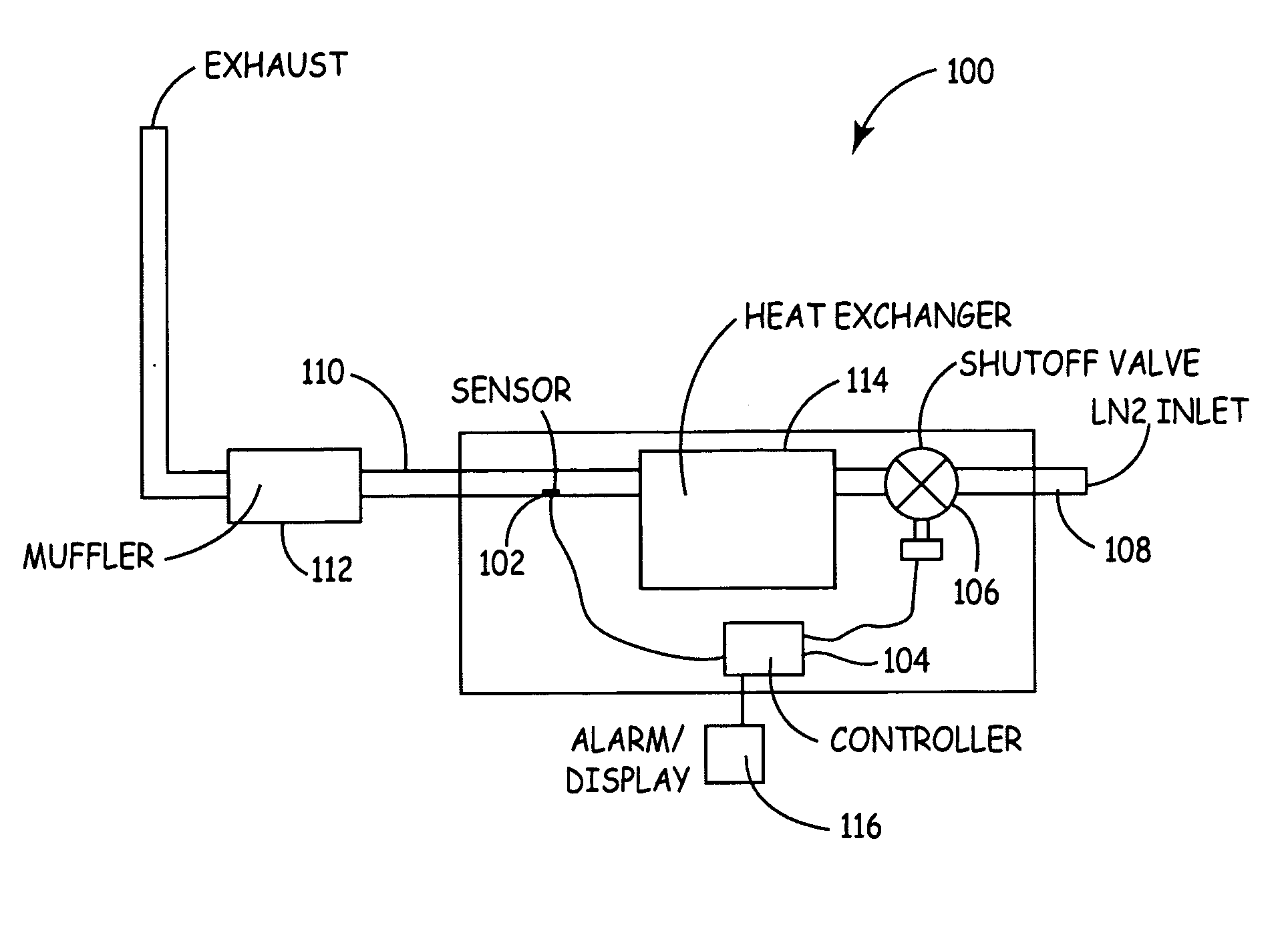
[0005] The present invention provides a system and method for preventing blow-by of liquefied gases, which senses the occurrence of blow-by and shuts off the source of the liquefied gas. In accordance with a preferred embodiment of the present invention, a system for preventing blow-by of LN2 is provided, which includes a temperature sensor located near an exhaust line of a heat exchanger, a shutoff valve located in an inlet line, and a controller coupled to the temperature sensor and the shutoff valve. The sensor measures the temperature of the exhaust, and provides a signal to the controller that indicates if the temperature of the exhaust approaches the temperature of LN2 . If the exhaust temperature approaches the temperature of LN2 , the controller sends a signal to the shutoff valve, which causes the valve to close and stops the flow of LN2 to the heat exchanger involved. The controller can also send an alarm signal to a display, which indicates to a user that the blow-by is occurring. If the exhaust temperature increases significantly above the temperature of LN2 (e.g., blow-by is no longer occurring), the controller can send a second signal to the shutoff valve, which causes the valve to open and resume the flow of LN2 .

Problems solved by technology

A significant problem that arises with the use of liquefied gases is commonly referred to as “blow-by”.
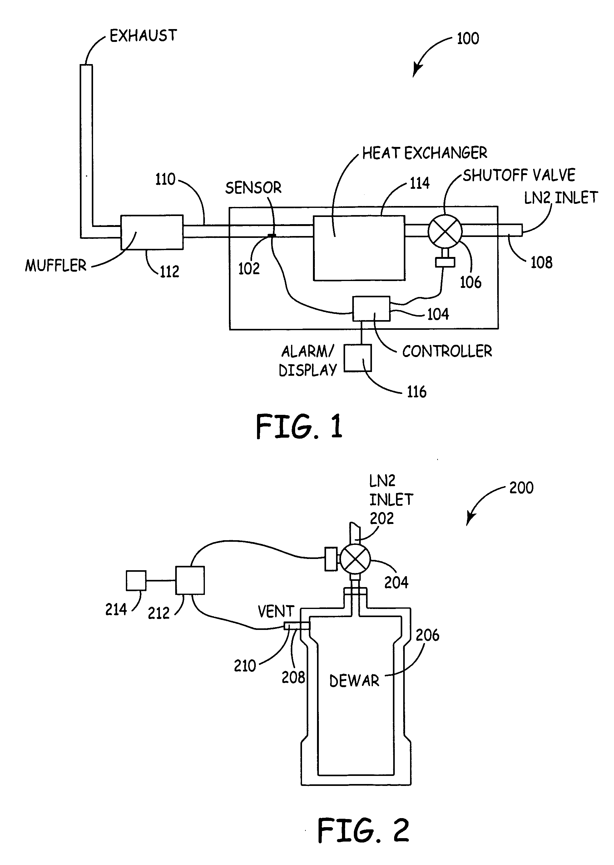
However, if the Dewar or other receiving vessel is filled to capacity, excess LN2 (rather than nitrogen gas) begins to blow-by or exit through the vent.
In less serious cases, the vented LN2 can rain down as super-cooled droplets that “burn” personnel and damage equipment.
In the more severe cases of blow-by (e.g., while filling a Dewar), large amounts of LN2 can be released to the surrounding environment in an uncontrolled fashion and produce a large, dangerous cloud of boiling white LN2 “smoke”.
Such large amounts of vented LN2 can result in serious bodily injuries such as bums and asphyxiation, severe damage to equipment, and can require a full-blown response by local authorities along with their hazardous materials cleanup teams.
Also, liquefied gases such as LN2 are relatively expensive to procure, and the economic cost due to blow-by is a significant expense to have to incur.
However, if the heat exchanger is overwhelmed with the incoming LN2 (e.g., the heat exchange rate is too slow), the excess LN2 (rather than the gaseous nitrogen) begins to blow-by or exit through the exhaust system to the surrounding environment or the outside air.
Monitoring the output of the exhaust is problematic, because these vents are typically located outside the buildings involved, and the vented LN2 can thus be difficult to see or hear.
Consequently, a significant amount of LN2 can be released and wasted due to blow-by, which also creates a substantial safety risk.

Method used


Image

  • System and method for preventing blow-by of liquefied gases
  • System and method for preventing blow-by of liquefied gases

Examples


Embodiment Construction

[0009] With reference now to the figures, FIG. 1 depicts a pictorial representation of an example system 100 for preventing blow-by of a liquefied gas, which can be used to implement a preferred embodiment of the present invention. For this illustrative embodiment, LN2 is used as a coolant in an example heat transfer application. As such, system 100 includes a temperature sensor 102 connected to an input of a controller unit 104. For example, controller unit 104 can be implemented with a suitable digital or analog process controller, microcontroller, digital processor, etc. An output of controller unit 104 is connected to an input of a shutoff valve 106. The shutoff valve 106 is located in series between an inlet tube 108 and a heat exchanger 114, and the temperature sensor 102 is coupled to an exhaust tube 110 of the heat exchanger 114, so that temperature sensor 102 can sense the temperature of the exhaust tube 110 at that location. As an option, the controller unit 104 is also co...


PUM


Abstract

A system and method for preventing blow-by of liquefied gases is disclosed, which senses the occurrence of blow-by and shuts off the source of the liquefied gas. As one example, a system for preventing blow-by of LN2 is disclosed, which includes a temperature sensor located near an exhaust line of a heat exchanger, a shutoff valve located in an inlet line, and a controller coupled to the temperature sensor and the shutoff valve. The sensor measures the temperature of the exhaust, and provides a signal to the controller that indicates if the temperature of the exhaust approaches the temperature of LN2. If the exhaust temperature approaches the temperature of LN2, the controller sends a signal to the shutoff valve, which causes the valve to close and stops the flow of LN2 to the heat exchanger involved. The controller can also send an alarm signal to a display, which indicates to a user that the blow-by is occurring. If the exhaust temperature increases significantly above the temperature of LN2 (e.g., blow-by is no longer occurring), the controller can send a second signal to the shutoff valve, which causes the valve to open and resume the flow of LN2.

Description

FIELD OF THE INVENTION [0001] The present invention relates generally to the process control field, and more specifically, but not exclusively, to a system and method for preventing blow-by of liquefied gases. BACKGROUND OF THE INVENTION [0002] Liquefied gases, such as liquid nitrogen (LN2), liquid helium or liquid oxygen, are used in a wide range of cryogenic (extremely cold) applications. For example, LN2 is often used as a coolant for sensitive electronic sensors, low noise amplifiers, semiconductor product testing, and other industrial applications. Also, LN2 is used for cryogenics research, preserving biological materials, freezing food products, and heat transfer applications that require the extremely low temperatures involved. [0003] A significant problem that arises with the use of liquefied gases is commonly referred to as “blow-by”. For example, when LN2 is transferred from one containment vessel to another (e.g., storage tank to a Dewar), a vent is provided in the receiv...

Claims


Application Information

Patent Timeline
Patent Type & Authority Applications(United States)
IPC IPC(8): B65B1/20
CPCF17C5/02F17C2221/011F17C2221/014F17C2223/0161F17C2223/033F17C2225/0161F17C2270/05F17C2250/032F17C2250/0408F17C2250/0439F17C2250/075F17C2270/02F17C2225/033
Inventor HARTNEY, NICHOLAS A.WEBB, WINSTON S.CUTTING, GUS W.
Owner HONEYWELL INT INC
Learn More