
Faraday Shield Disposed Within An Inductively Coupled Plasma Etching apparatus

a plasma etching and inductively coupled technology, applied in the direction of electrical apparatus, basic electric elements, electric discharge tubes, etc., can solve the problems of affecting the etching process, interfering with the etching process, and not necessarily uniform field, so as to prevent the erosion of the etching chamber window

Inactive Publication Date: 2007-08-09
LAM RES CORP
View PDF4 Cites 37 Cited by
  • Summary
  • Abstract
  • Description
  • Claims
  • Application Information

AI Technical Summary

Benefits of technology

The present invention provides an apparatus and method for maintaining the condition of an etching chamber window by configuring a Faraday shield between the window and a plasma. This avoids problems of the prior art such as erosion of the window and shunting heat away from the window. The technical effects of the invention include improved plasma processing efficiency and reduced damage to the etching chamber window.

Problems solved by technology

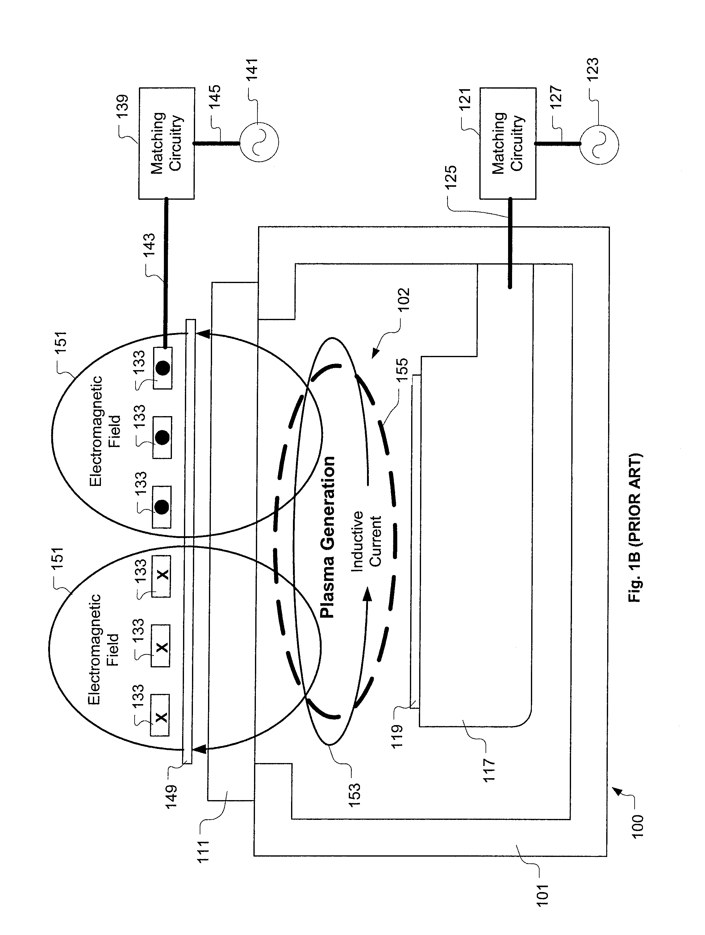
This field is not necessarily uniform.
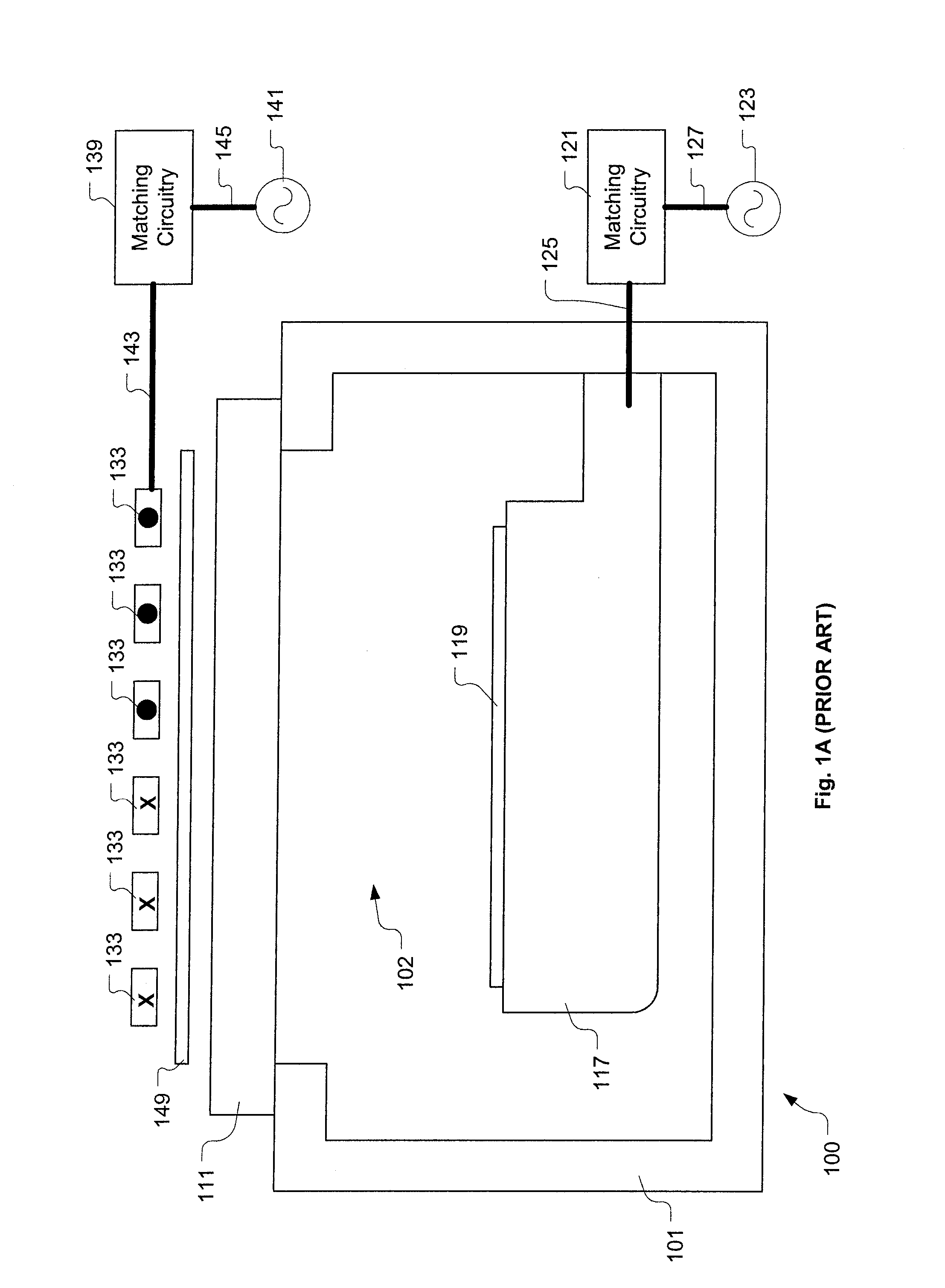
Adherence of non-volatile reaction products to the window 111 may interfere with the etching process.
Excessive deposition 157 may result in particles flaking off the window 111 onto the wafer 119, thus interfering with the etching process.
The presence of unwanted species in the chamber internal cavity 102 is particularly undesirable because it leads to poor reproducibility of the etching process conditions and resulting wafer 119 characteristics.
The quartz window 111 is relatively expensive and costly to replace upon failure.
Thus, when exposed to a high thermal output associated with certain etching processes, the ceramic window 111 is more susceptible to experiencing differential thermal expansion leading to cracking and failure.

Method used


Image

  • Faraday Shield Disposed Within An Inductively Coupled Plasma Etching apparatus
  • Faraday Shield Disposed Within An Inductively Coupled Plasma Etching apparatus
  • Faraday Shield Disposed Within An Inductively Coupled Plasma Etching apparatus

Examples


Embodiment Construction

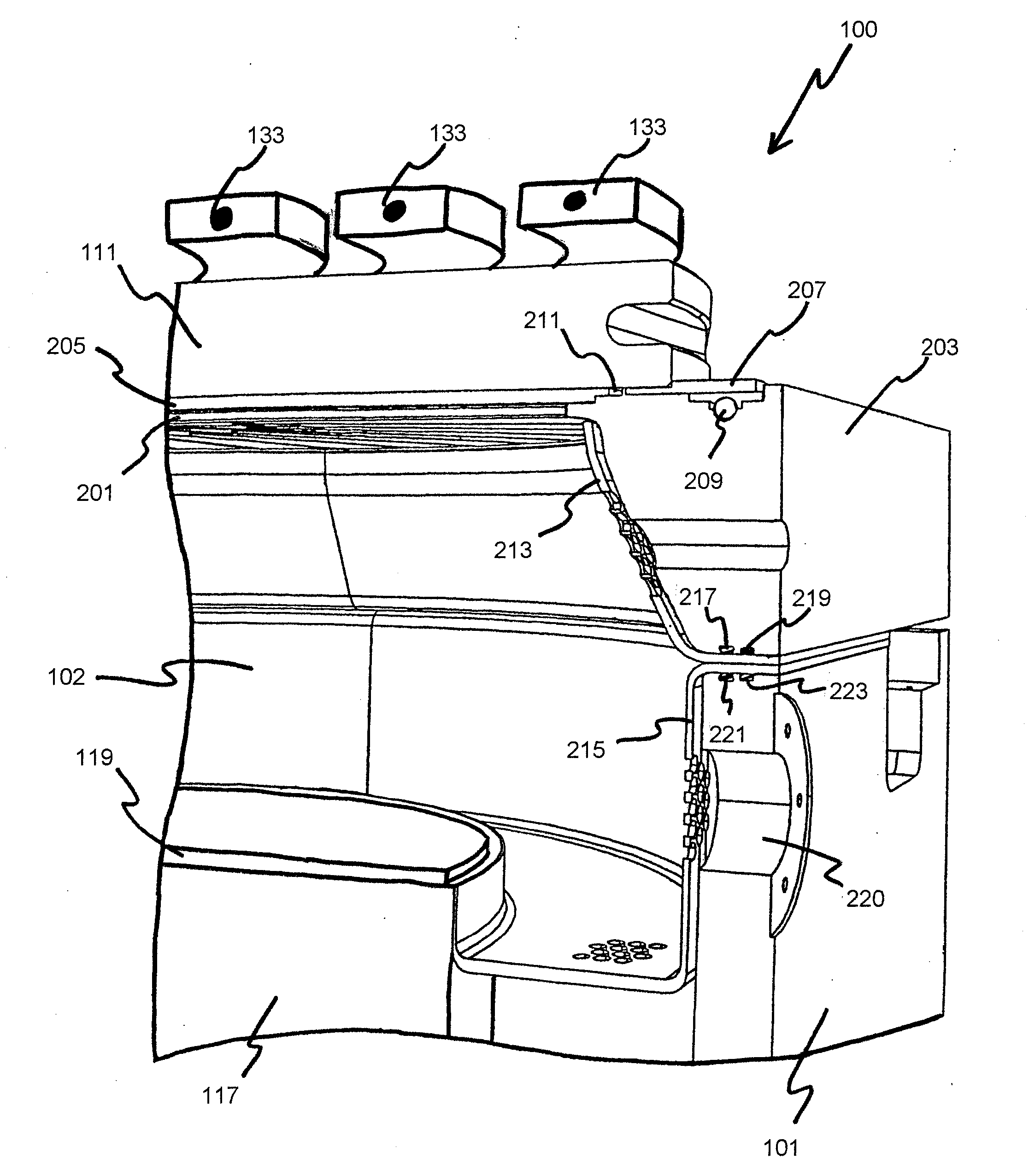
[0049] An invention is disclosed for apparatuses and methods for positioning and using a Faraday shield in direct exposure to a plasma within an inductively coupled plasma etching apparatus. Broadly speaking, the present invention maintains a condition of an etching chamber window. Configuring the Faraday shield between the window and the plasma prevents erosion of the window resulting from plasma sputter and shunts heat generated by an etching process away from the window. The present invention solves one problem of the prior art by reducing the window replacement frequency driven by erosion of the window due to plasma sputter. The present invention solves another problem of the prior art by allowing the use of a larger variety of window materials through a relaxation of thermal performance requirements afforded by the shunting of heat away from the window.

[0050] In the following description, numerous specific details are set forth in order to provide a thorough understanding of t...


PUM

PropertyMeasurementUnit
distanceaaaaaaaaaa
thicknessaaaaaaaaaa
thicknessaaaaaaaaaa

Abstract

An apparatus and method is provided for positioning and utilizing a Faraday shield in direct exposure to a plasma within an inductively coupled plasma etching apparatus. Broadly speaking, the Faraday shield configuration maintains a condition of an etching chamber window. At a minimum, positioning the Faraday shield between the window and the plasma prevents erosion of the window resulting from plasma sputter and shunts heat generated by an etching process away from the window.

Description

CLAIM OF PRIORITY [0001] This application is a divisional application of U.S. patent application Ser. No. 10 / 232,564, filed on Aug. 30, 2002, from which priority under 35 U.S.C. 120 is claimed, which is incorporated herein by reference in its entirety for all purposes.BACKGROUND OF THE INVENTION [0002] 1. Field of the Invention [0003] The present invention relates generally to semiconductor fabrication, and more particularly, to apparatuses and methods for using a Faraday shield in direct exposure to a plasma within an inductively coupled plasma etching apparatus. [0004] 2. Description of the Related Art [0005] In semiconductor manufacturing, etching processes are commonly and repeatedly carried out. As is well known to those skilled in the art, there are two types of etching processes: wet etching and dry etching. Dry etching is typically performed using an inductively coupled plasma etching apparatus. [0006]FIG. 1A shows an inductively coupled plasma etching apparatus 100, in acco...

Claims


Application Information

Patent Timeline
Patent Type & Authority Applications(United States)
IPC IPC(8): C23F1/00
CPCH01J37/32633H01J37/321
Inventor COMENDANT, KEITHSTEGER, ROBERT J.
Owner LAM RES CORP
Learn More