
Ink-droplet ejecting apparatus

a technology of ejecting apparatus and droplets, which is applied in the direction of printing, other printing apparatus, etc., can solve the problems of limit on increasing the driving voltage, and achieve the effects of increasing the drive frequency, shortening the entire pulse width, and increasing the recording speed

Active Publication Date: 2007-08-09
BROTHER KOGYO KK
View PDF9 Cites 5 Cited by
  • Summary
  • Abstract
  • Description
  • Claims
  • Application Information

AI Technical Summary

Benefits of technology

[0008] An object of the present invention is to realize an ink-droplet ejecting apparatus which is an ink ejecting apparatus ejecting a plurality of ink droplets for one dot, and which is capable of increasing the drive frequency by making short (shortening) the entire pulse width, and increase the recording speed. It should be noted that parenthesized reference numerals assigned to elements shown below are only examples of the elements, and are not intended to limit the elements.
[0009] According to a first aspect of the present invention, there is provided an ink-droplet ejecting apparatus (101) which ejects a plurality of ink droplets of an ink to form one dot onto a recording medium (P), including a pressure chamber (36) in which the ink is filled and a piezoelectric actuator (2) which faces the pressure chamber (36), and which changes a volume of the pressure chamber (36) according to a driving pulse signal for ejecting the ink droplets to form one dot, wherein the driving pulse signal includes a plurality of main pulses (Pm) which are successive with intervals to eject the ink droplets, and a stabilizing pulse (Ps) which is inserted between the main pulses (Pm), and which suppresses a residual vibration of the ink, in the pressure chamber (36), generated by one of the main pulse (Pm) applied before the stabilizing pulse, and a last main pulse, among the main pulses, is adjusted to suppress the residual vibration of the ink in the pressure chamber (36), generated by a main pulse applied before the last main pulse, and to prevent vibration generated by the last main pulse from remaining.
[0010] In order to shorten a driving cycle for forming one dot, it is necessary to shorten an one-way propagation time (a time in which a pressure wave generated due to a displacement of the piezoelectric actuator (2) is propagated in one way through an ink channel) with respect to a pulse width of each of a plurality of pulse signals. As a method for shortening the one-way propagation time, it is possible to shorten ink channels including the pressure chamber (36). However, in this case, since a length of the pressure chamber (36) which is affected by the displacement of the piezoelectric actuator (2) becomes short, it is necessary to increase a driving voltage applied to the piezoelectric actuator (2) to impart the same ejecting pressure. However, there are limitations on increasing the driving voltage. On the other hand, in the ink-droplet ejecting apparatus (101) of the present invention, at the time of forming one dot, a plurality of ink droplets is ejected by the plurality of main pulses (Pm), and by inserting the stabilizing pulse (Ps) between the main pulses (Pm), the residual vibration of the ink is suppressed. Furthermore, since the last main pulse among the plurality of main pulses (Pm) suppresses the residual vibration of the ink in the pressure chamber generated by the main pulses which were applied before the last main pulse, and has the pulse width such that no vibration by the last main pulse is remained, it is possible to suppress effectively the residual vibration of the ink by less number of the stabilizing pulses (Ps) as compared to the number of the main pulses (Pm). As a result, it is possible to shorten an overall pulse width, and to drive with a short cycle, thereby enabling to increase the recording speed. Furthermore, since it is not necessary to shorten the ink channel to shorten the driving cycle, it is not necessary to shorten a length of the pressure chamber (36). Consequently, it is not necessary to increase a driving voltage to impart the same ejecting pressure.

Problems solved by technology

However, there are limitations on increasing the driving voltage.

Method used


Image

  • Ink-droplet ejecting apparatus
  • Ink-droplet ejecting apparatus
  • Ink-droplet ejecting apparatus

Examples


Embodiment Construction

[0035] A basic embodiment of the present invention will be described below by referring to FIG. 1 to FIG. 9.

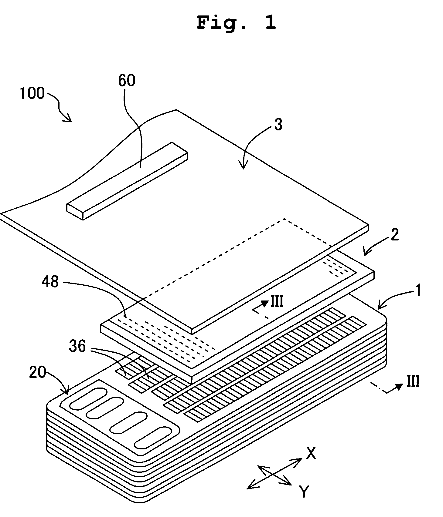
[0036] As shown in FIG. 9, an ink-droplet ejecting apparatus 101 includes a carriage 102 which is movable in a scanning direction (left and right direction in FIG. 9), an ink-jet head 100 which is movable along with the carriage 102, and which jets an ink onto a recording paper P, paper transporting rollers 103 which transport the recording paper P in a paper feeding direction (paper-surface frontward direction in FIG. 9), and the like. Moreover, the ink-jet head 100, while moving integrally with the carriage 102 in the scanning direction, performs printing on the recording paper P from nozzles 4 arranged on a lower surface thereof (refer to FIG. 3). The recording paper P with the printing performed thereon by the ink-jet head 100 is discharged in the paper feeding direction by the paper transporting rollers 103.

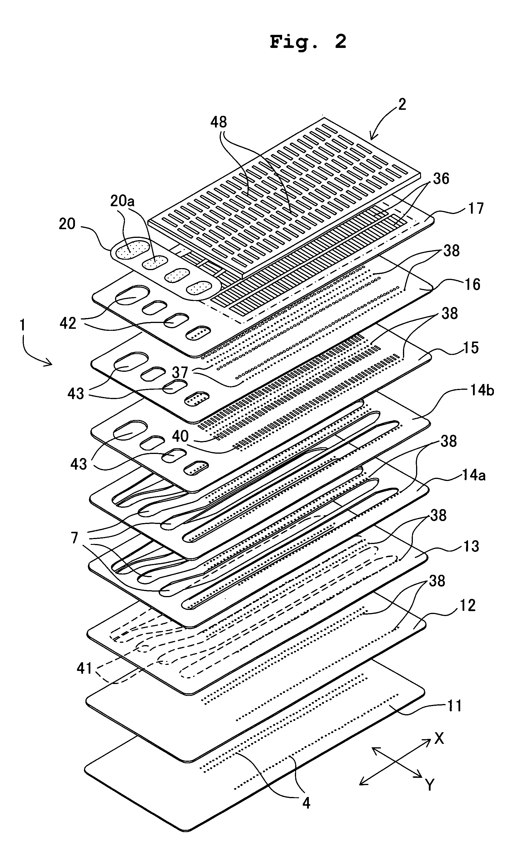
[0037] Next, the ink-jet head 100 will be described below. As s...


PUM


Abstract

A driving pulse signal for forming one dot includes a first, a second, and a third main pulses applied intermittently with an intervals to eject an ink droplet, and a stabilizing pulse which is inserted between the main pulses, and which suppresses a residual vibration of an ink in a pressure chamber, generated by a main pulse applied previously. The third main pulse suppresses the residual vibration of the ink generated by the second main pulse, and also a pulse width of the third pulse is adjusted such that there is no residual vibration remained, due to application of the last main pulse. Consequently, it is possible to suppress effectively the residual vibration of the ink by the less number of the stabilizing pulses compared to the number of main pulses. As a result, an overall pulse width becomes short, and it is possible to increase the recording speed.

Description

CROSS REFERENCE TO RELATED APPLICATION [0001] The present application claims priority from Japanese Patent Application No. 2006-018742, filed on Jan. 27, 2006, the disclosure of which are incorporated herein by reference in its entirety. BACKGROUND OF THE INVENTION [0002] 1. Field of the Invention [0003] The present invention relates to an ink-droplet ejecting apparatus of an ink-jet type. [0004] 2. Description of the Related Art [0005] In hitherto known ink-jet printers, which are ink-droplet ejecting apparatuses, an ink-jet head is used which ejects an ink droplet from a nozzle by changing a volume of a pressure chamber in which an ink is filled, by displacing an electromechanical transducer (transducer element) such as a piezoelectric element by applying a driving pulse signal. [0006] In the above mentioned ink-jet head, a gradation control in which, a dot diameter is changed is carried out. For forming one dot by a plurality of ink droplets, the driving pulse signal is set such ...

Claims


Application Information

Patent Timeline
Patent Type & Authority Applications(United States)
IPC IPC(8): B41J29/38
CPCB41J2/04516B41J2/04581B41J2/04588B41J2002/14225B41J2/14209B41J2002/14217B41J2/04596
Inventor IRIGUCHI, AKIRA
Owner BROTHER KOGYO KK
Learn More