Method and apparatus for analyzing characteristic information of object with the use of mutual interaction between ultrasound wave and light

a technology of characteristic information and mutual interaction, applied in the field of internal structure analysis, can solve the problems of difficult observation of the oct, inability to provide a technique for obtaining information on scattering light, and extreme disturbed optical coherence, so as to achieve the effect of obtaining characteristic information and good resolution

Inactive Publication Date: 2007-08-16
OLYMPUS MEDICAL SYST CORP
View PDF5 Cites 93 Cited by
  • Summary
  • Abstract
  • Description
  • Claims
  • Application Information

AI Technical Summary

Benefits of technology

[0020] The present invention has been made in light of the problems as described above, and has as its object to provide an object information analyzing apparatus, an endoscope system and an object...

Problems solved by technology

On the other hand, it is difficult for the OCT to enable observation at a depth of about 2 mm or more under the mucous membrane and to provide good quality image of tumor tissue, such as cancer.
This is because the optical coherence is extremely disturbed by the influence of absorption or serious scattering of blood in the deep part of a living organism and tumor tissue.
However, the prior art references mentioned above are only specialized in light-absorbing imaging and do not provide a technique for obtaining information on scattering light caused by the configuration or structure of tissue.
The plurality of light sources and detectors employed in the prior art disclosed in this Japanese Patent Laid-Open Publication No. 2000-197635 raise some problems, for example, that lots of labor and time have ...

Method used


Image

  • Method and apparatus for analyzing characteristic information of object with the use of mutual interaction between ultrasound wave and light
  • Method and apparatus for analyzing characteristic information of object with the use of mutual interaction between ultrasound wave and light
  • Method and apparatus for analyzing characteristic information of object with the use of mutual interaction between ultrasound wave and light

Examples


first embodiment

[0111] Referring to FIGS. 1-5, a first embodiment of the present invention will now be described.

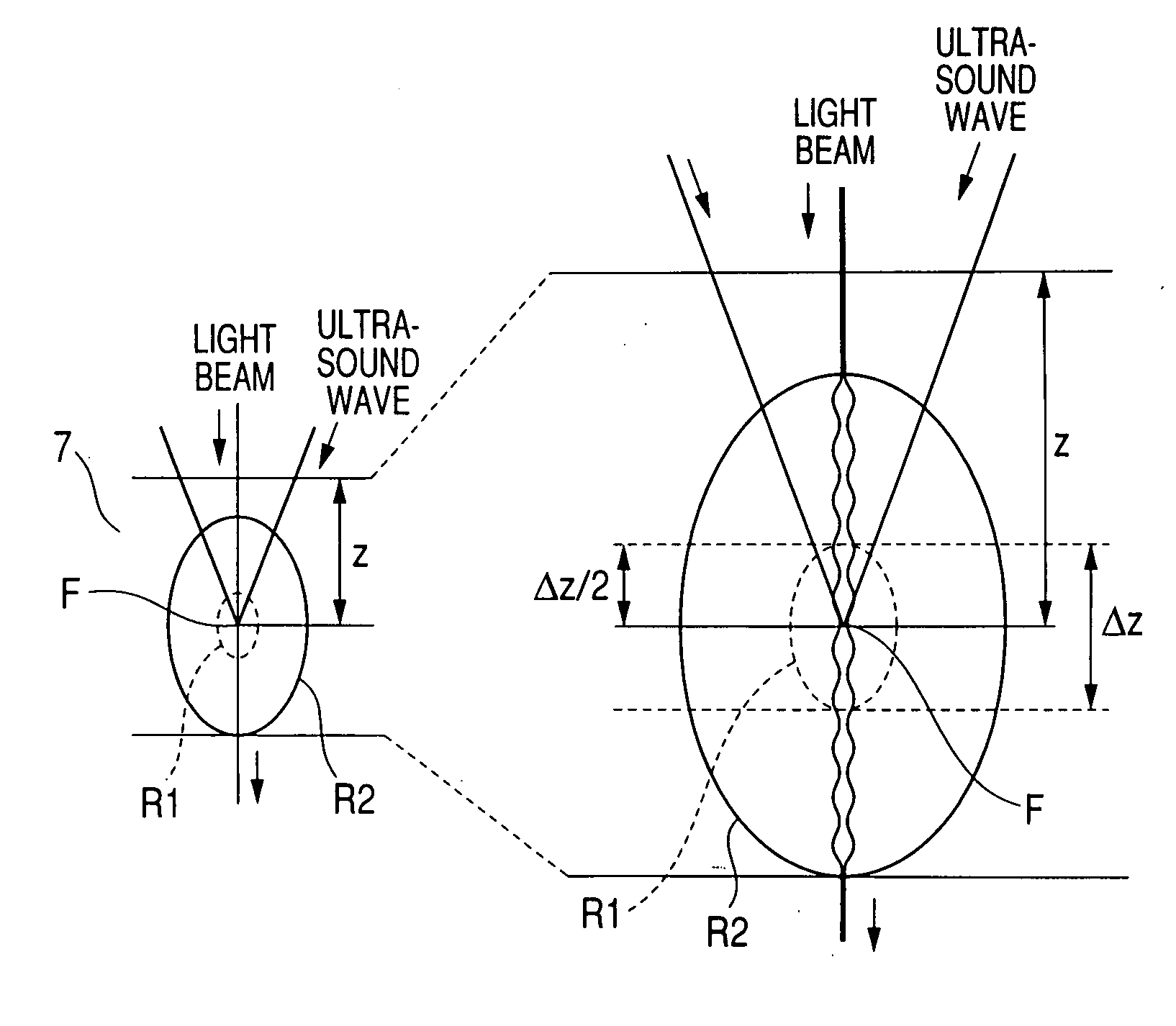
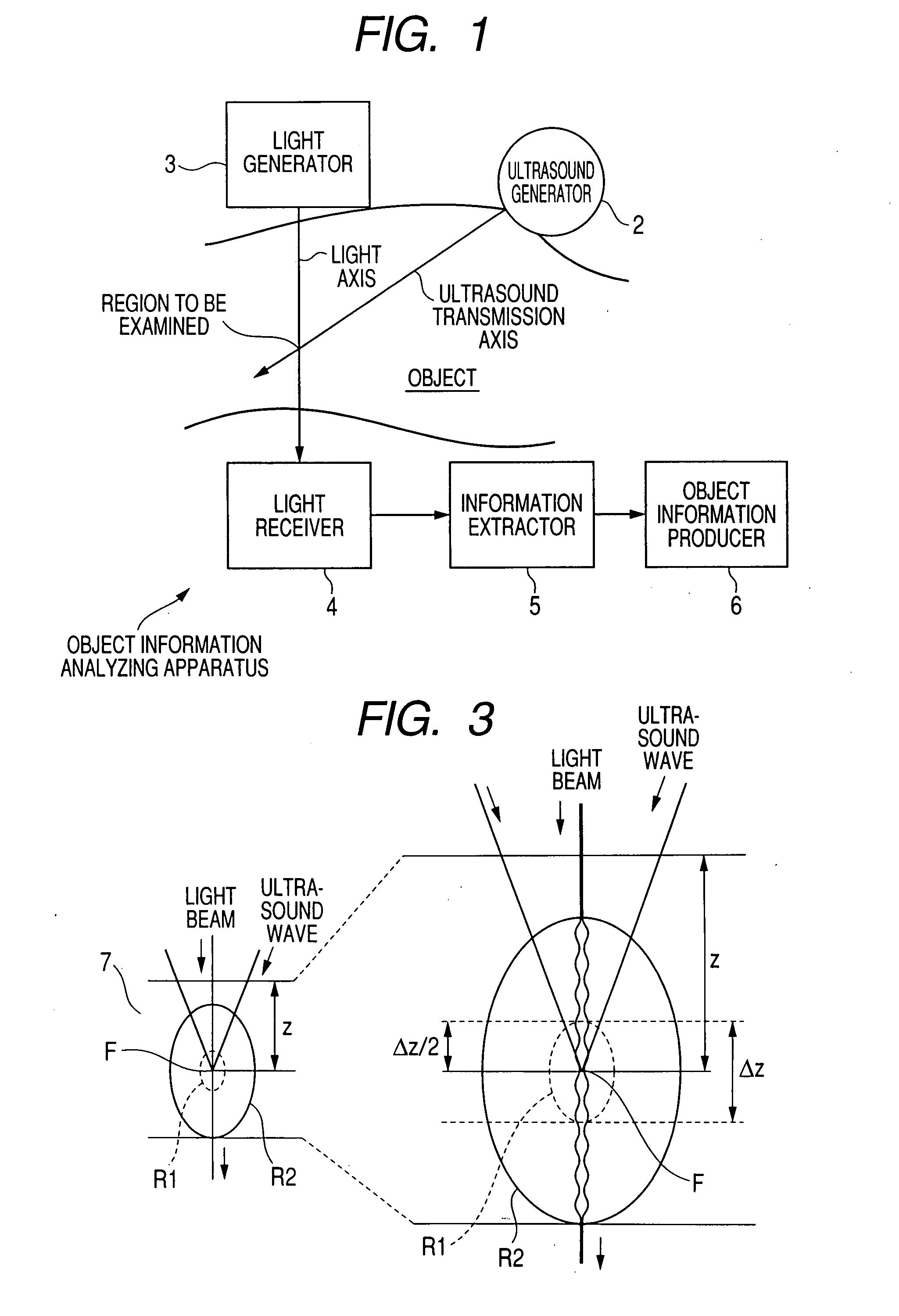
[0112]FIG. 1 is a block diagram illustrating a basic configuration of an object information analyzing apparatus of the present invention. As shown in FIG. 1, the object information analyzing apparatus of the present invention is provided with an ultrasound generator 2 capable of generating ultrasound waves so as to be transmitted into an object along a predetermined ultrasound transmission axis, and a light generator 3 capable of generating a light beam that reaches a region to be examined in an object to which the ultrasound waves generated by the ultrasound generator 2 are transmitted.

[0113] The object information analyzing apparatus is also provided with a light receiver 4 which is arranged being oriented to the region to be examined so as to receive the light beam that has been generated by the light generator 3 and passed through the region to be examined, and an information extra...

second embodiment

[0239] Referring to FIGS. 6 and 7, a second embodiment of the present invention will now be described.

[0240]FIG. 6 illustrates an optical imaging apparatus AP2 according to the second embodiment.

[0241] The first embodiment has been arranged so as to detect the transmission beam that has transmitted through the tissue 7, and serves as the observation beam, whereas the present embodiment is so arranged that a light beam is radiated to a tissue 7 of a living organism and a beam returning to the side of radiation is detected as the observation beam. In particular, a photo detector 4a according to the present embodiment forms a reflected-light receiver. In the present embodiment, the identical or similar components or processes are given the same references as in the first embodiment for the sake of simplification or omission of explanation.

[0242] In FIG. 6, some references are different from those in FIG. 2, such as a distance “D1” between a light source 3b and a half mirror 13.

[024...

third embodiment

[0346] Referring to FIGS. 14-16, a third embodiment of the present invention will now be described.

[0347]FIG. 14 illustrates an optical imaging apparatus AP7 according to the third embodiment of the present invention. In the present embodiment, an optical fiber is used to achieve more reduction in the size, in particular, reduction in the size of a two-dimensional scanning portion. In the present embodiment, the identical or similar components or processes are given the same references as in the first and second embodiments for the sake of simplification or omission of explanation.

[0348] The optical imaging apparatus AP7 is provided with the light source (or laser device) 3a for emitting a laser beam, for example, to be radiated to the tissue 7.

[0349] A light beam emitted from the light source 3a is incident on an end face of an optical fiber 52a for directing the light beam and divided into two beams in an optical coupler 53 provided midway through the optical fiber 52a. One bea...


PUM


Abstract

An apparatus analyzes information indicative of a characteristic of a region to be examined an object. The apparatus comprises an ultrasound generator generating an ultrasound wave toward the region within the object and a light generator generating light toward the region. The ultrasound sound generated is transmitted toward the region. The apparatus further comprises a light receiver, information acquiring unit, and information producer. The light receiver receives light coming from the region and outputting an electric signal corresponding to the received light. The information acquiring unit acquires information indicative of scattering of the light at the region by using either the signal outputted from the light receiver or the light coming from the region. The information producer produces the information indicative of the characteristic of the region based on the scattering information acquired by the information acquiring unit.

Description

CROSS REFERENCES TO RELATED APPLICATIONS [0001] This application is based on and claims the benefit of priorities from earlier Japanese Patent Application No. 2006-012898 filed Jan. 20, 2006, and Japanese Patent Application No. 2007-005680 filed Jan. 15, 2007, Japanese Patent Application No. 2007-005678 filed Jan. 15, 2007, and Japanese Patent Application No. 2007-005679 filed Jan. 15, 2007, the descriptions of which are incorporated herein by reference. BACKGROUND OF THE INVENTION [0002] 1. Field of the Invention [0003] The present invention relates to a technique for analyzing an internal structure of an object to be diagnosed, and in particular, to a method and apparatus for analyzing information indicative of a characteristic of a region to be examined of an object to be diagnosed with the use of mutual interaction between the ultrasound waves and light, and an endoscope system that uses such an analyzing technique. [0004] 2. Description of Related Art [0005] Recently, various t...

Claims


Application Information

Patent Timeline
IPC IPC(8): G01N21/86G01V8/00
CPCA61B5/0048A61B5/0059A61B5/0066A61B5/0075A61B8/12A61B5/0095A61B5/7257A61B5/726A61B5/0084G09F15/0087G09F15/0012G09F15/0037G09F15/0068G09F19/02
Inventor IGARASHI, MAKOTO
Owner OLYMPUS MEDICAL SYST CORP
Why Eureka
Try Eureka