Over-current detection circuit and method for power-supply device

Inactive Publication Date: 2007-08-16
GOOGLE LLC
View PDF1 Cites 17 Cited by
  • Summary
  • Abstract
  • Description
  • Claims
  • Application Information

AI Technical Summary

Benefits of technology

[0022]As described above, in accordance with the over-current detection method for a power-supply device of the present invention, since both of the ON-voltage of the main MOSFET and the ON-voltage of the sense MOSFET used for obtaining the reference voltage for over-current setting are DC voltages, it is easy to compare them in a comparator. In this way, since variations of the ON-voltage due to process variations of the ON-resistance of the MOSFET or the influence of switching noise is suppressed, the invention can provide an over-current detection method for a power-supply device that enables stable over-current detection with high detection accuracy.
[0023]Sinc

Problems solved by technology

However, the conventional over-current detection method for a power-supply device that uses the ON-voltage of a main MOSFET, described in the above Background Art, is problematic in that the ON-voltage is easily influenced by process variations of the ON-resistance of the main MOSFET.
The method disclosed in JP Patent Publication (Kokai) No. 2003-60449 A is problematic in that over-current detection accuracy is low and stable over-current detection is difficult, since the reference voltage is influenced by vari

Method used


Image

  • Over-current detection circuit and method for power-supply device
  • Over-current detection circuit and method for power-supply device
  • Over-current detection circuit and method for power-supply device

Examples


first embodiment

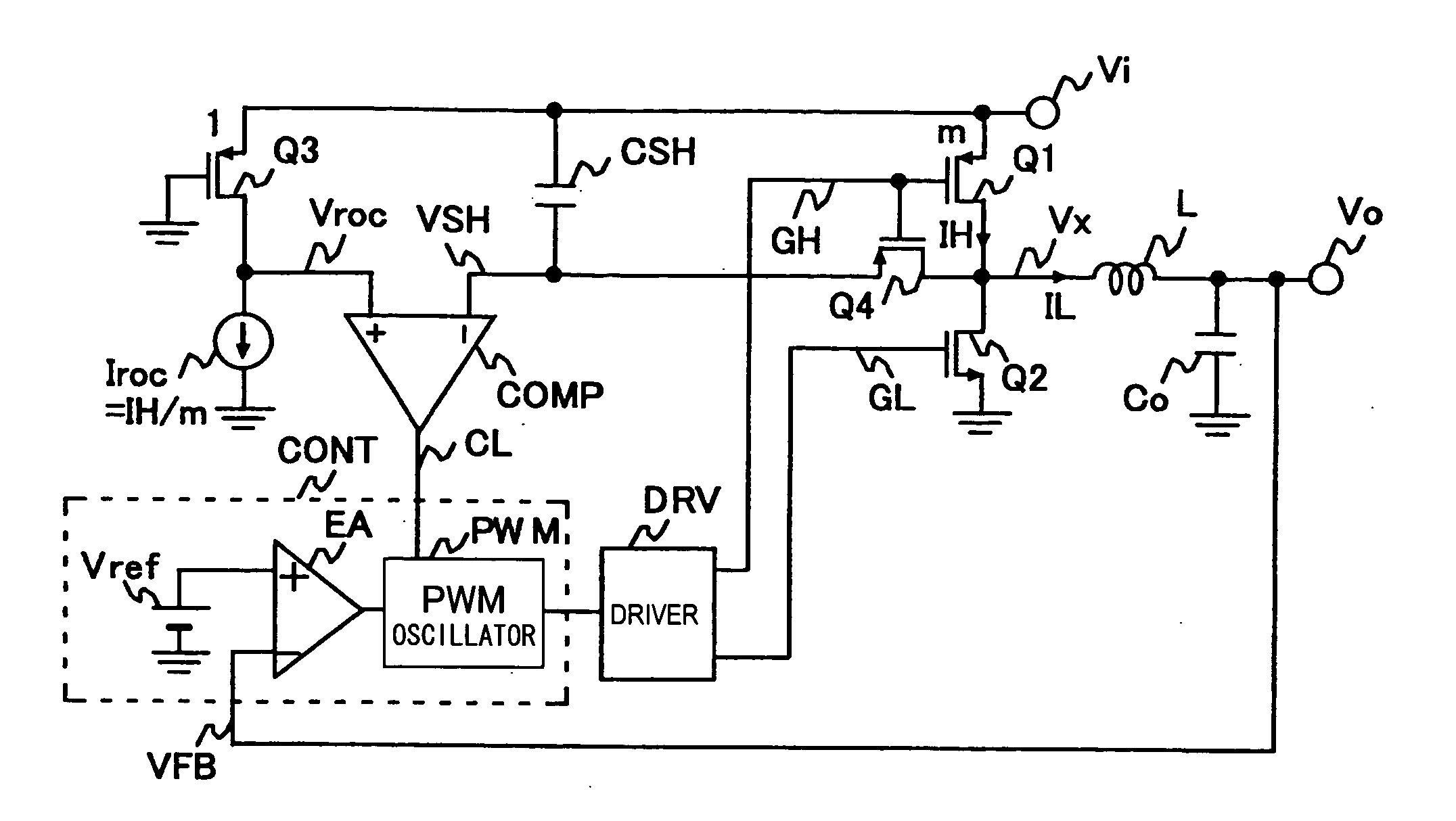
[0038]FIG. 1 shows a circuit diagram of a power-supply device containing an over-current detection circuit according to a first embodiment of the present invention. In FIG. 1, character Vi denotes an input terminal and character Vo denotes an output terminal. The input terminal Vi is connected to a high side power MOSFET (Q1), and a low side power MOSFET (Q2) is connected to ground. The midpoint between the power MOSFET (Q1) and the power MOSFET (Q2) is connected to an LC smoothing filter (power system output filter) comprising an inductor L and a capacitor Co, and the midpoint of the LC smoothing filter is connected to the output terminal Vo and one input (−) of an error amplifier EA.

[0039]The other input (+) to the error amplifier EA is connected to a reference voltage Vref. The output from the error amplifier EA is connected to a pulse-width modulation (PWM) oscillator PWM and a driver circuit DRV. The PWM is connected to the gate of the power MOSFET (Q1) and the power MOSFET (Q2...

second embodiment

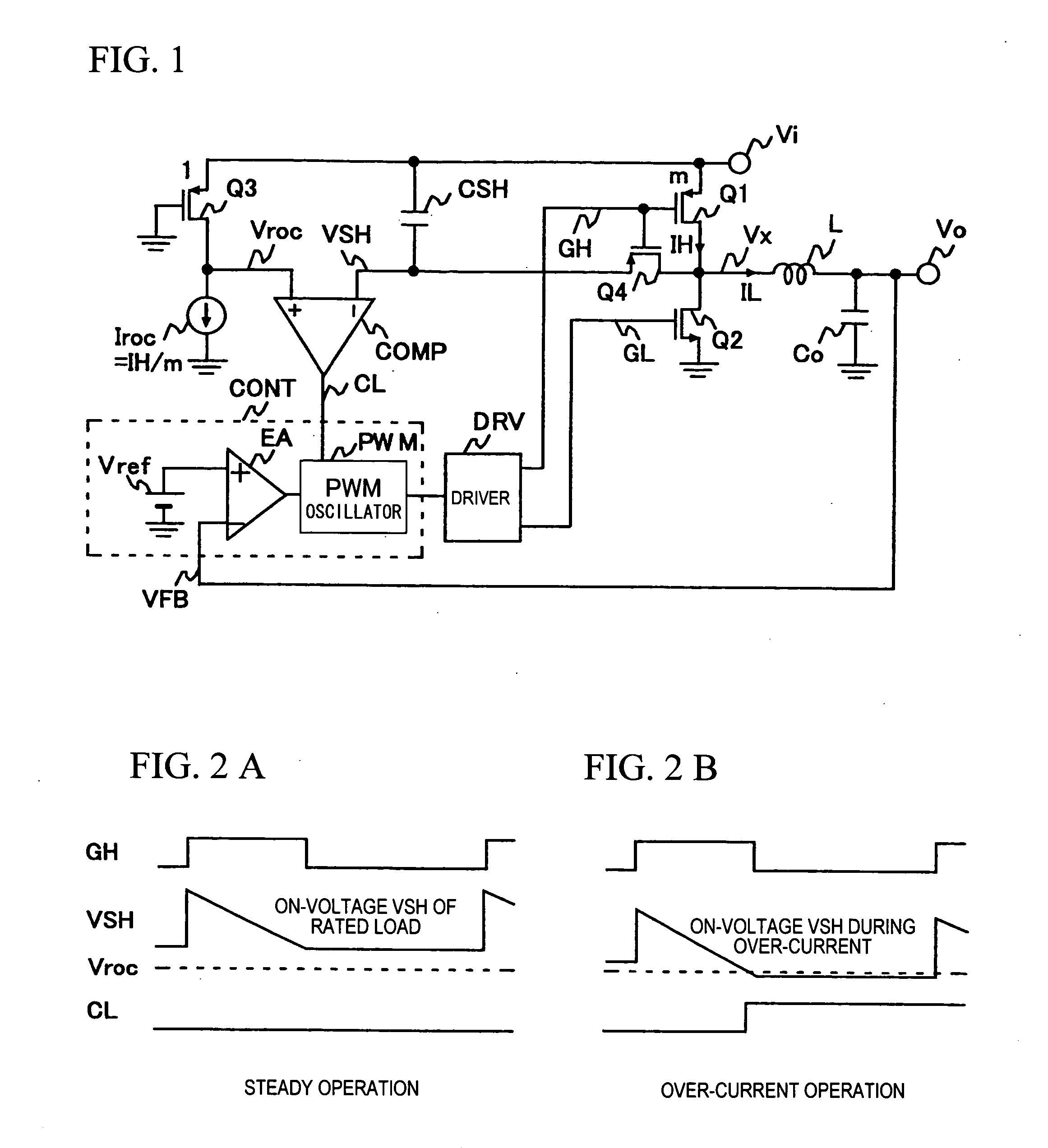
[0054]FIG. 4 shows a circuit diagram of a power-supply device containing an over-current detection circuit according to a second embodiment of the present invention. In the figure, since a control circuit CONT and a driver DRV are the same as those shown in FIG. 1, the illustration thereof is omitted. FIG. 5 shows operating waveforms of a principal portion of the circuit shown in FIG. 4.

[0055]When the circuit shown in FIG. 4 and the circuit shown in FIG. 1 are compared, only the difference is that a resistor Rfil is connected in series with the switching MOSFET (Q4). Structured in this way, the present embodiment has the advantageous effect that, in addition to the advantageous effect of the first embodiment of the present invention, over-current detection can be achieved with a reduced ripple component and at a value closer to a DC voltage as the VSH in FIG. 5 shows, by smoothing the on-period waveform of the high power MOSFET (Q1) of the voltage VSH shown in FIG. 4 via a filtering...

third embodiment

[0056]In an over-current detection circuit according to a third embodiment of the present invention, an over-current value is detected not using a peak current. FIG. 6 shows a circuit diagram of a power-supply device containing an over-current detection circuit according to the third embodiment of the present invention. However, in the figure, since a control circuit CONT and a driver DRV are the same as those shown in FIG. 1, the illustration thereof is omitted. FIG. 7 shows operating waveforms of a principal portion of the circuit shown in FIG. 6.

[0057]The over-current detection circuit shown in FIG. 6 differs from the over-current detection circuits shown in FIGS. 1 and 4 in that a gate driving signal G4 of a switching MOSFET (Q4) is set separately from a gate driving signal GH of a high side power MOSFET (Q1). Further, as shown in FIG. 7, it is structured such that the on-period of the gate driving signal G4 (generating means will be described later) of the switching MOSFET (Q4)...


PUM


Abstract

An over-current detection circuit using the ON-voltage of a main MOSFET is provided, which is resistant to process variations of a main MOSFET and is not easily influenced by switching noise. Separately from a main MOSFET (Q1), a sense MOSFET (Q3) whose size is 1/m of the main MOSFET is provided and it is caused to be normally on. A DC ON-voltage generated when a current that is 1/m of an over-current value is caused to flow through the sense MOSFET is obtained as a reference voltage for over-current setting. The ON-voltage when the main MOSFET is on is sampled and held, and it is obtained as a DC voltage. These DC voltages are compared in a comparator (COMP).

Description

BACKGROUND OF THE INVENTION[0001]1. Field of the Invention[0002]The present invention relates to an over-current detection circuit and method for a power-supply device. In particular, it relates to an over-current detection circuit and method for a power-supply device, whereby, when detecting an over-current using the ON-voltage of a main MOSFET, variations of the ON-voltage due to process variations of the ON-resistance of the main MOSFET or the influence of switching noise is reduced, thereby stabilizing the detection accuracy.[0003]2. Background Art[0004]Conventionally, a built-in power supply of an LSI circuit such as an FPGA or CPU chip is suitable for a compact or low-cost system / unit due to reduction of external components and for high-speed current response (high di / dt) of a load side. As an over-current detection method in such case, the ON-voltage of a main MOSFET is used. The following methods are known as such a method using the ON-voltage of a main MOSFET.[0005]Accordin...

Claims


Application Information

Patent Timeline
IPC IPC(8): H02H3/08H02H9/02
CPCH02M1/32H02M2001/0009H02M3/156H02M1/0009
Inventor SASE, TAKASHIKANOUDA, AKIHIKOKAWAKUBO, YOSUKEKURITA, KOZABURO
Owner GOOGLE LLC
Why Eureka
Try Eureka