Optical information device and information recording and reproduction device
an information recording and reproduction device technology, applied in the direction of optical recording heads, data recording, instruments, etc., can solve the problems of reducing the gain of tracking control, reducing the effect of tracking control gain, and increasing the relative amount of production errors with respect to track pitch. , to achieve the effect of reducing the fluctuation of tracking error signal amplitude and high reliability
- Summary
- Abstract
- Description
- Claims
- Application Information
AI Technical Summary
Benefits of technology
Problems solved by technology
Method used
Image

Examples
embodiment 1
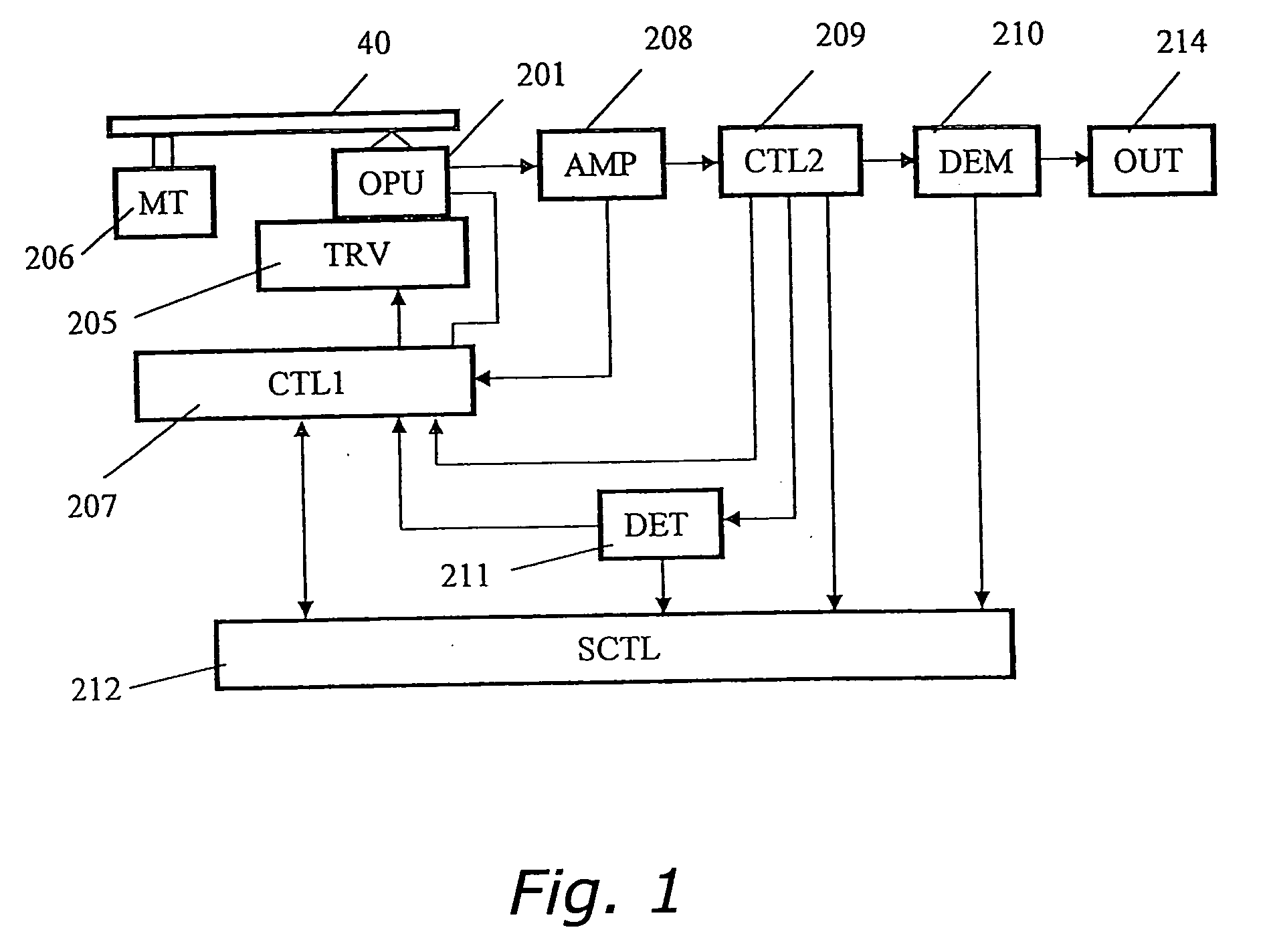
[0066] FIG.1 is a diagram of the structure of an optical information device in Embodiment 1 of the present invention.
[0067] An optical pickup head device 201 (also called an optical pickup) irradiates an optical recording medium 40 with a laser beam having a wavelength μ of 405 nm, and a signal recorded to the optical recording medium 40 is reproduced. A transfer controller 205 moves the optical pickup device 201 in the radial direction of the optical recording medium 40 in order to record or reproduce information at the desired location on the optical recording medium 40. A motor 206 that drives the optical recording medium 40 rotates the optical recording medium 40. A controller 207 controls the optical pickup head device 201, the transfer controller 205, and the motor 206.
[0068] An amplifier 208 amplifies a signal read by the optical pickup head device 201. An output signal from the amplifier 208 is inputted to a controller 209. On the basis of this signal, the controller 209 p...
embodiment 2
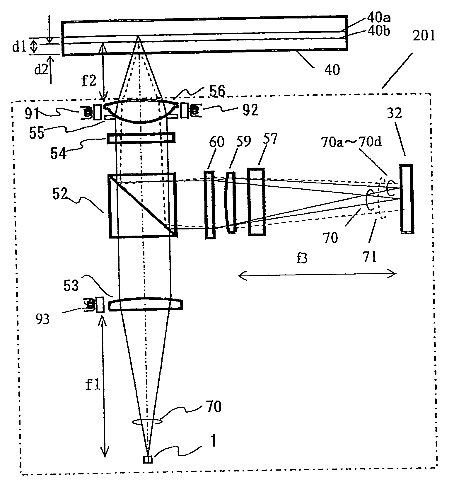
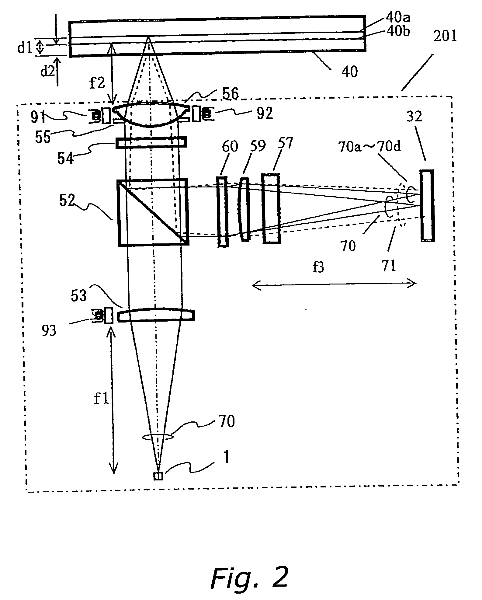
[0079]FIG. 8 is a schematic diagram of the relationship between a photodetector 33 used in this embodiment and the beams 70, 71, and 70a to 70d received by the photodetector 33.
[0080] The difference between the optical pickup in this embodiment and the optical pickup in Embodiment 1 is that the photodetector 33 is used instead of the photodetector 32. The difference between the photodetector 32 and the photodetector 33 is that light receivers 33i to 331 are disposed at positions in substantially axial symmetry with light receivers 33e to 33h with respect to the center of the beam 71 reflected by the information recording plane 40b, where the beam is not focused. The TE signal when this photodetector 33 is used is obtained by (I33e−I33j)−(I33f−I33i)−K·((I33h−I33k)−(I33g−I33l)), where K is a real number.
[0081] In this case, stray light from the beam 71 reflected by the information recording plane 40b where the light receivers 33e to 33h for producing the TE signal are incident is ca...
embodiment 3
[0082]FIG. 9 is a schematic diagram of the relationship between a photodetector 34 used in this embodiment and the beams 70 and 70a to 70n received by the photodetector 34.
[0083] The difference between the optical pickup in this embodiment and the optical pickup in Embodiment 1 is that a diffraction grating 61 (not shown) is used instead of the diffraction grating 60, and the photodetector 34 is used instead of the photodetector 32. The diffraction grating 60 in Embodiment 1 could have a lateral cross sectional shape that was either a simple grooved shape, or a stepped or serrated blazed shape, but the diffraction grating 61 in this embodiment has a simple groove-shaped cross section that generates ± diffracted light. This diffraction grating 61 also has a total of four different regions 60a to 60d, just as did the diffraction grating 60 in FIG. 3.
[0084] Next, the beam split by the diffraction grating 61 will be described. 70a is the +1st-order diffracted light, and 70e the −1st-o...
PUM
 Abstract
Description
Claims
Application Information
PatSnap Eureka turns technology decisions into work you can execute. Powered by our Innovation Knowledge Graph, it runs expert workflows across engineering, life sciences, materials and intellectual property. Get your review-ready output in minutes.


