Optical delivery systems and methods of providing adjustable beam diameter, spot size and/or spot shape

a beam diameter and spot technology, applied in the field of optical delivery, can solve the problems of limiting the speed at which the beam spot can be adjusted, system using a zoom lens has additional parts, and system building and operation is expensiv

Active Publication Date: 2007-08-16
IRIDEX CORP
View PDF15 Cites 97 Cited by
  • Summary
  • Abstract
  • Description
  • Claims
  • Application Information

AI Technical Summary

Benefits of technology

[0030] The innovations herein solve the aforementioned problems by modifying optical characteristics of beams, by varying objects such as fibers or other optical elements, adjusting one or more etendue-modifying aspects, etc., to achieve a final beam diameter of desired size and shape.

Problems solved by technology

While these methods vary the beam spot size satisfactorily, these methods involve moving elements with large moments of inertia.
Having to move elements makes the system expensive to build and operate and, more importantly, limits the speed at which the beam spots can be adjusted.
A system using a zoom lens has additional problems stemming from the second law of thermodynamics which, in the context of optics, makes the source the brightest part of the system.
Because the use of larger spot sizes requires proportionally higher power to cause the desired effect on the target (e.g., drilling a hole or heating tissues), this inverse relationship between large spot size and small numerical aperture poses a problem when there is an intermediate structure between the source and target.
For example, these intermediate structures can often absorb enough of the delivered light to cause damage to itself and the system.
The defocus technique has the disadvantage of deviating from the image plane and therefore an uncertain change in irradiance distribution.
There is also the loss of the sharp edge definition of the spot and the safety issue of the positioning a small beam at some location other than the treatment plane.
Both the turret and zoom lens configurations involve movement of powered optics and therefore the associate disadvantages in reliability and alignment.
Also the lens systems are complex and the optical performance is a weighted compromise over all possible configurations.
Moreover, traditional approaches relate only to limited aspects of the overall etendue transfer characteristics of interest, such as magnification or aperture size change in one optical element as described immediately above.
Therefore, drawbacks exist for system that are unable to change beam diameter, spot size and spot shape via changes to one or more of fiber diameter (core size), effective fiber diameter (and / or effective numerical aperture), aperture size, and entendue-modifying aspects such as aperture placement, among others that may be varied vis-á-vis application of the above-stated relationships to elements or articles of optical systems.

Method used


Image

  • Optical delivery systems and methods of providing adjustable beam diameter, spot size and/or spot shape
  • Optical delivery systems and methods of providing adjustable beam diameter, spot size and/or spot shape
  • Optical delivery systems and methods of providing adjustable beam diameter, spot size and/or spot shape

Examples


Embodiment Construction

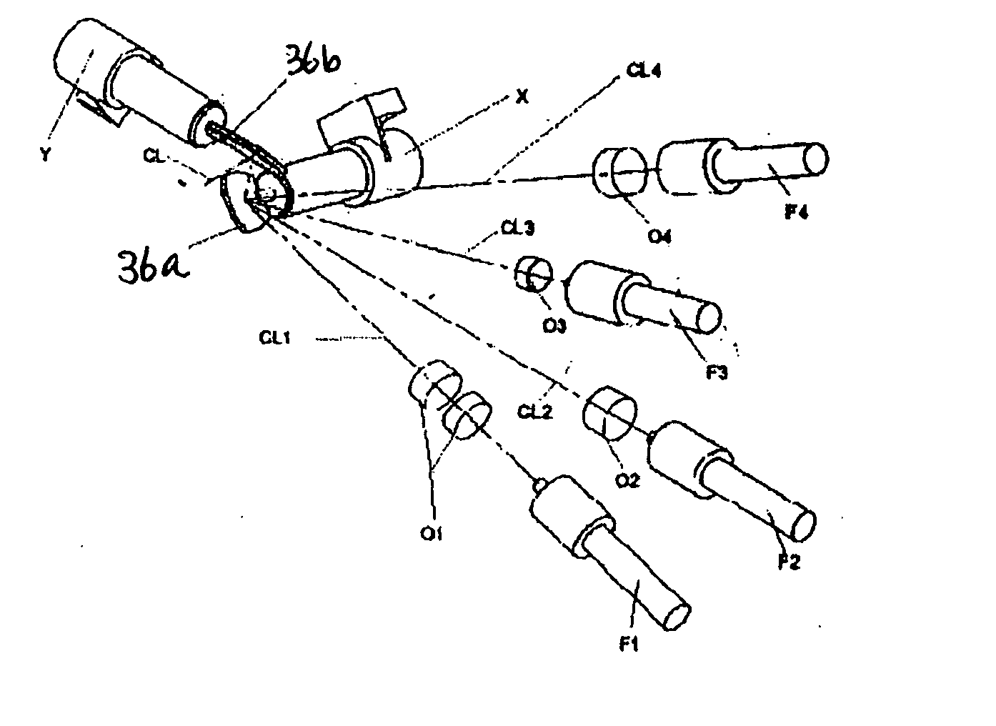
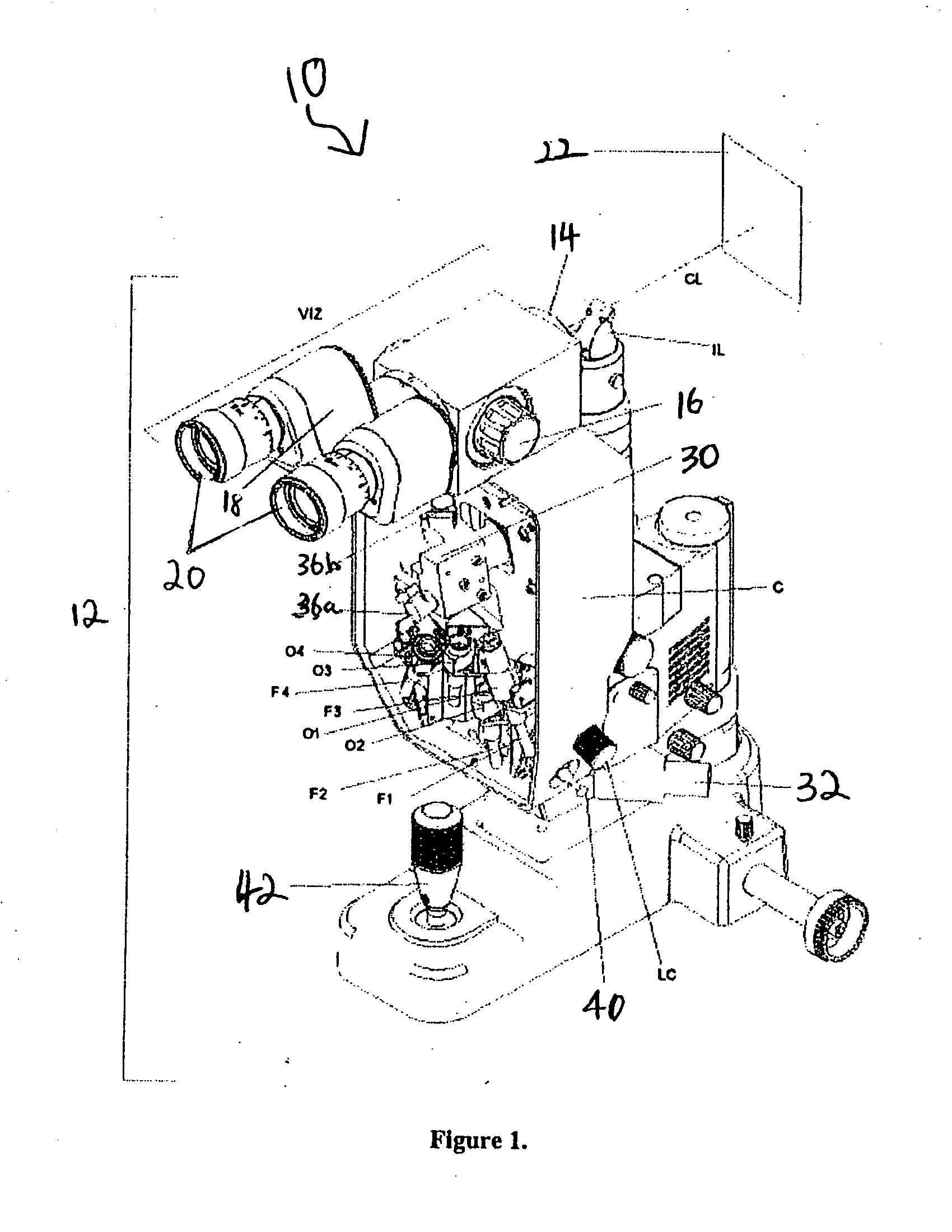
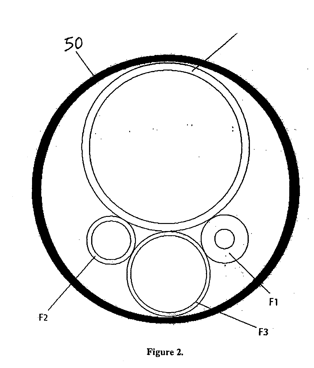
[0046] The innovations herein achieve adjustment of spot size and shape via techniques that differ from traditional approaches. According to certain aspects of an exemplary spot size adjustment embodiment discussed herein, multiple fibers may be used wherein some of the separate fibers can be of different size. Further, according to some of these aspects, the output of each fiber is directed to a dedicated optical path. Each of these optical paths can have a different magnification that results in a desired spot size at the treatment area. The multiple fiber and the separate output optical paths take advantage of the underutilized dynamic range of both the input and output galvanometric systems.

[0047] At the input to the fiber, a beam-deviating component such as a galvo system may be used for switching the delivered light on and off by directing the beam onto and off of the fiber face. Typically the fibers are small in diameter (<500 um) and the capability of the galvo scan coupled...


PUM


Abstract

An optical device and method for varying an optical characteristic of an optical beam can include a plurality of optical fibers each having an input end, an output end, and a core, wherein each of the optical fibers has an effective area and a numerical aperture, and a beam deviating component for moving at least one of the optical fiber input ends and the optical beam relative to each other such that the optical beam selectively enters the input ends one at a time and is transmitted out the output ends one at a time, wherein at least one of the effective areas and the numerical apertures varies among the plurality of optical fibers such that the optical beam transmitted out of the output ends has a varying optical characteristic.

Description

CROSS REFERENCE TO RELATED APPLICATIONS [0001] This application claims the benefit of priority U.S. Provisional Application No. 60 / 758,802 filed on Jan. 12, 2006, the entire content of which is incorporated herein by reference.BACKGROUND OF THE INVENTION [0002] 1. Field of the Invention [0003] The present invention pertains to systems and methods for producing adjustable beams, spot sizes and spot shapes on a target. [0004] 2. Background Information [0005] Today, many ophthalmic treatments involve using an optical beam to treat a target (e.g., a patient's eye). For example, diabetic retinopathy and age-related macular degeneration are subject to photocoagulative treatment with visible laser light. In performing these treatments, it is sometimes advantageous to be able to use beams of different sizes depending on the particular type of treatment and the condition of the patient. Traditionally, adjustable optical beam diameters have been produced by using a fixed light source with eit...

Claims


Application Information

Patent Timeline
Patent Type & Authority Applications(United States)
IPC IPC(8): G02B6/26
CPCA61B3/0008G02B26/105A61F9/008A61F9/00821A61F9/00823A61F9/009A61F2009/00863A61F2009/00872A61F2009/00897G02B6/32G02B6/3512G02B6/3548G02B6/357G02B6/3582A61B3/135
Inventor ANDERSEN, DAN E.ANGELEY, DAVID G.GOODING, PHILIPWILTBERGER, MICHAEL W.MORDAUNT, DAVID H.
Owner IRIDEX CORP
Why Eureka
Try Eureka