Method of molding for microneedle arrays

a technology of microneedle arrays and molds, which is applied in the field of manufacturing microneedle arrays, can solve the problems of limited number of molecules demonstrated, difficult manufacturing of needle passageways, and limited size of needle passageways

Inactive Publication Date: 2007-08-16
3M INNOVATIVE PROPERTIES CO
View PDF96 Cites 90 Cited by
  • Summary
  • Abstract
  • Description
  • Claims
  • Application Information

AI Technical Summary

Benefits of technology

[0007] The present invention provides methods of molding microneedle arrays. In one embodiment, the microneedle array is manufactured by providing a negative mold insert characterized by the negative image of microneedle topography wherein at least one negative image of a microneedle is characterized by an aspect ratio of between about 2 to 1 and about 5 to 1. The negative moldinsert is transferred into an injection molding apparatus to define a structured surface of a negative mold cavity. The temperature of the negative mold cavity is raised above the softening temperature of the moldable plastic material. In one embodiment, the temperature of the negative mold cavity is raised about 10° C. above the softening temperature of the moldable plastic material. The moldable plastic material is heated to at least the molten temperature of the moldable plastic material in a chamber separate from the negative mold cavity. The molten plastic material is then injected into the heated negative mold cavity and allowed to fill at least about 90 percent of the volume of the negative indentations defined by the negative mold insert. The negative mold cavity is cooled to a temperature at least below the softening temperature of the moldable plastic material and the molded microneedle array or positive mold member is detached from the negative mold insert. In one embodiment, this allows the microreplicated part to be separated from the negative mold insert without distortion.

Problems solved by technology

Only a limited number of molecules with demonstrated therapeutic value can be transported through the skin, even with the use of approved chemical enhancers.
Because the needles are small, the passageways formed in the needles must be limited in size.
As a result, the passageways of the needles can be difficult to manufacture because of their small size.
Issues associated with microneedle devices include the ability to make precise arrays having microstructured features using biologically acceptable materials.

Method used


Image

  • Method of molding for microneedle arrays
  • Method of molding for microneedle arrays
  • Method of molding for microneedle arrays

Examples


examples

[0058] Examples 1-12

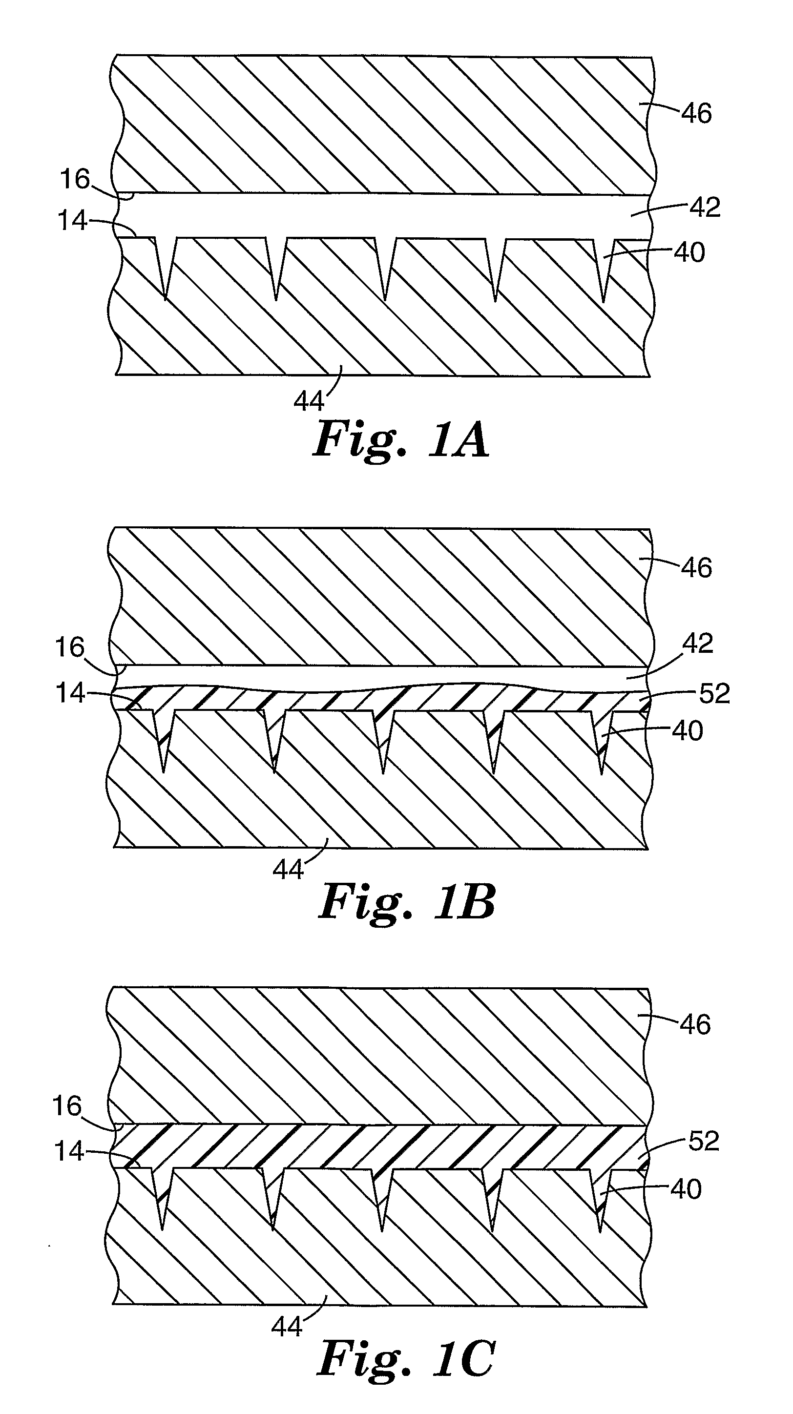
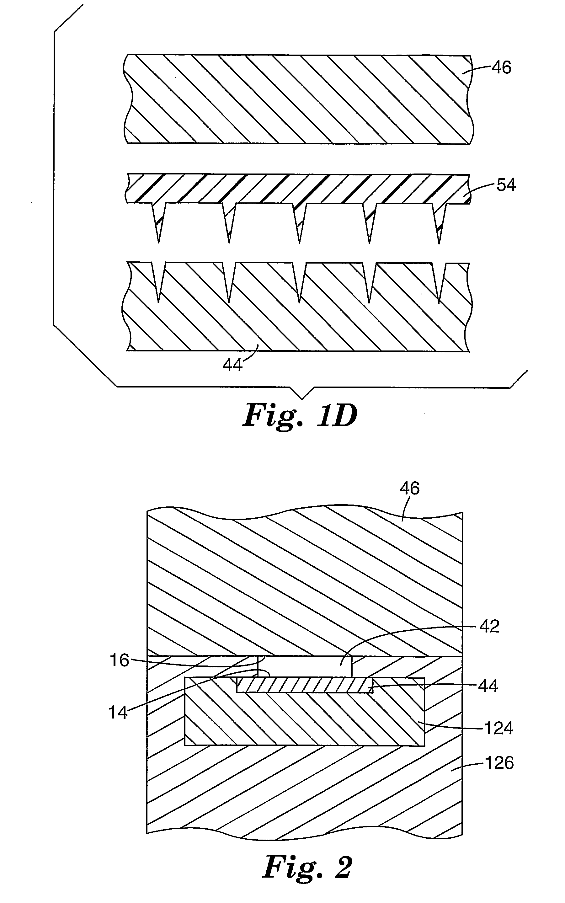
[0059] Molded microneedle arrays were prepared according to the general procedures described above using a 55-ton injection molding press (Milacon Cincinnati ACT D-Series Injection Molding Press) equipped with a thermocycling unit (Regoplas 301 DG Thermal Cycling Unit). Polycarbonate pellets were loaded into a reciprocating screw and heated until molten. The negative mold insert was heated to a specified temperature (hereafter referred to as the “mold temperature at injection”) above the softening temperature of the material to be molded. The molding cycle was initiated by closing the mold chamber, clamping the mold with 55 tons of force, and injecting a first portion (approx. 50-80% of the part size volume) of the total amount of material from the reciprocating screw into the negative mold insert. The first portion of material was injected into the negative mold insert at a fixed velocity (hereafter referred to as the “injection velocity”). After injecting the ...

examples c1-c2

[0063] Molded microneedle arrays were prepared according to the procedure described in Examples 1-12, with the exception that the mold temperature at injection on each array was reduced to 310° F. (154.4° C.) and 260° F. (126.7° C.) respectively. The comparative examples details of the injection velocity, pack pressure, hold time, mold temperature at injection, mold temperature at ejection, and resulting needle height for each example is shown in Table 1.

TABLE 1InjectionMoldMoldAverageVelocityPackHoldtemperaturetemperatureneedleExample[inches / sec,Pressuretimeat injectionat ejectionheightNumber(cm / sec)][psi, (Mpa)][sec][° F., (° C.)][° F., (° C.)][microns]10.50120004340280141(1.27)(81.6)(171.1)(137.8)20.50120006340280139(1.27)(81.6)(171.1)(137.8)30.50120002340280134(1.27)(81.6)(171.1)(137.8)40.50 80004340280133(1.27)(54.4)(171.1)(137.8)50.50160004340280141(1.27)(108.9) (171.1)(137.8)61.50120004340280139(3.81)(81.6)(171.1)(137.8)70.30120004340280141(0.76)(81.6)(171.1)(137.8)80.50120...

examples 13-16

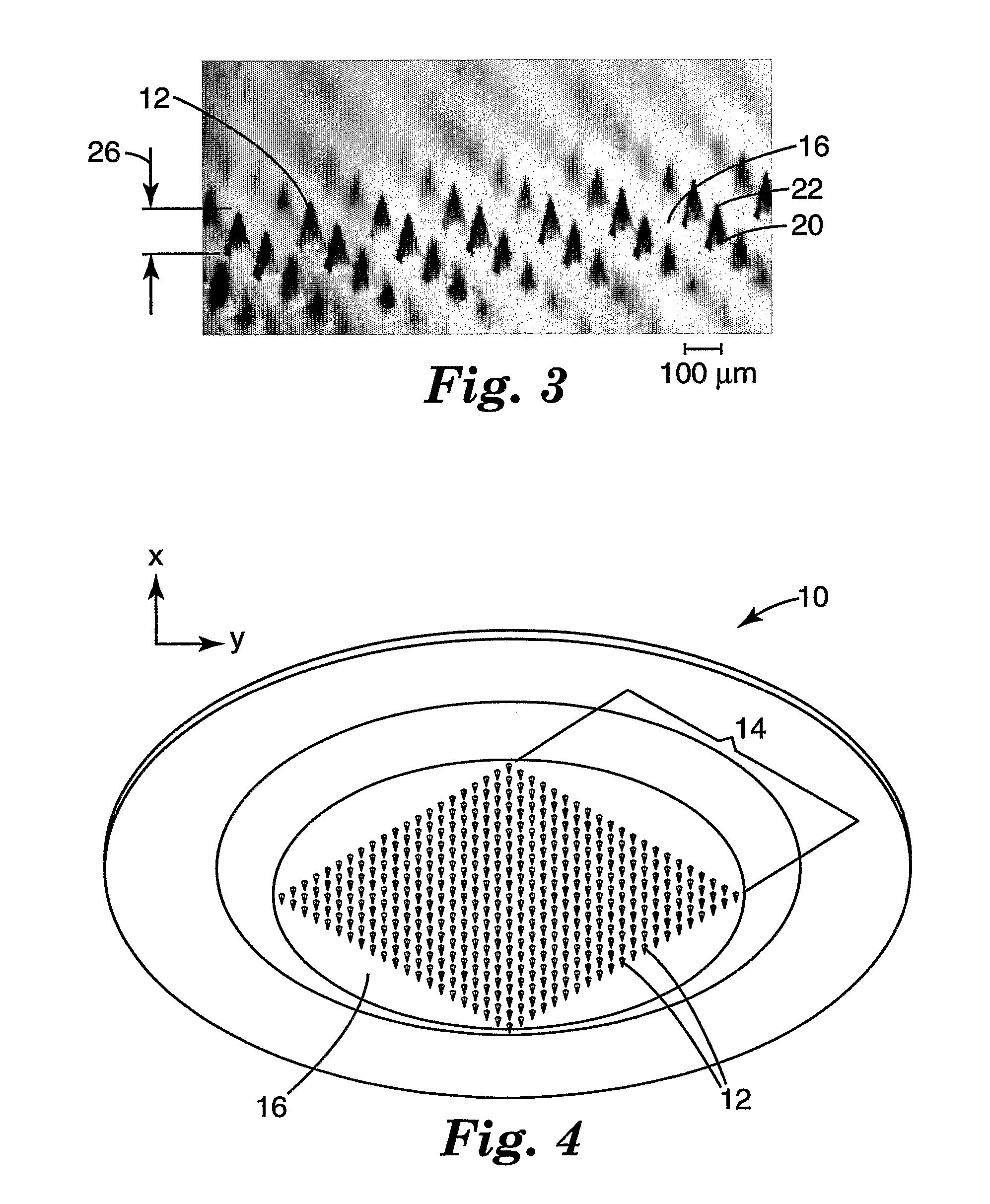
[0064] Molded microneedle arrays were prepared according to the procedure described in Examples 1-12, with the exception that individual needles on each array had a height of 375 microns and a base side-length of 125 microns. The needles were spaced in a regular array with a distance of 600 microns between the tips of adjacent needles. Details of the injection velocity, pack pressure, hold time, mold temperature at injection, and mold temperature at ejection used for each example is shown in Table 2.

TABLE 2InjectionMoldMoldAverageVelocityPackHoldtemperaturetemperatureneedleExample[inches / sec,Pressuretimeat injectionat ejectionheightNumber(cm / sec)][psi, (Mpa)][sec][° F., (° C.)][° F., (° C.)][microns]130.50140004340280323(1.27) (95.3)(171.1)(137.8)140.50160004340280322(1.27)(108.9)(171.1)(137.8)150.50160004360270335(1.27)(108.9)(182.2)(132.2)160.50160004370270332(1.27)(108.9)(187.8)(132.2)


PUM

PropertyMeasurementUnit
aspect ratioaaaaaaaaaa
softening temperatureaaaaaaaaaa

Abstract

A method of manufacturing a moldable microneedle array (54) is described comprising providing a negative mold insert (44) characterized by a negative image of microneedle topography wherein at least one negative image of a microneedle is characterized by an aspect ratio of between about 2 to 1 and about 5 to 1. The negative mold insert (44) is used to define a structured surface of a negative mold cavity (42). Molten plastic material is injected into the heated negative mold cavity. The molten plastic material is subsequently cooled and detached from the mold insert to provide a molded microneedle array (54). One manner of using microneedle arrays of the present invention is in methods involving the penetration of skin to deliver medicaments or other substances and/or extract blood or tissue through the skin.

Description

[0001] This application claims benefit of priority to U. S. Provisional Application Serial No. 60 / 546,780, filed Feb. 23, 2004.FIELD [0002] The present invention relates to the field of methods of manufacturing microneedle arrays. BACKGROUND [0003] Only a limited number of molecules with demonstrated therapeutic value can be transported through the skin, even with the use of approved chemical enhancers. The main barrier to the transport of molecules through the skin is the stratum corneum (the outermost layer of the skin). [0004] Devices including arrays of relatively small structures are sometimes referred to as microneedles, microneedle arrays, micro arrays, or micro-pins or the like. These structures have been disclosed for use in connection with the delivery of therapeutic agents and other substances through the skin and other surfaces. These medical devices pierce the stratum corneum by a plurality of microscopic slits in the outermost layer of skin to facilitate the transderma...

Claims


Application Information

Patent Timeline
Patent Type & Authority Applications(United States)
IPC IPC(8): A61M37/00A61B17/20A61B17/06A61M5/32B29C45/73C25D1/00C25D7/00B29C33/40B29C33/38B29C33/42B29C45/37B81C99/00
CPCA61B17/205C25D1/10A61B2017/00893A61M37/0015A61M2037/0053B29C33/3842B29C33/3857B29C33/42B29C45/2669B29C45/37B29C45/372B29C45/561B29C45/73B29C2045/0094B29C2045/7393B29L2031/753B29L2031/7544B29L2031/756B81B2201/055B81C99/0085A61B2017/00526
Inventor BOONE, MARY R.CARTER, CHAD J.FREDERICKSON, FRANKLYN L.
Owner 3M INNOVATIVE PROPERTIES CO
Why Eureka
Try Eureka