Direct digital synthesis radar timing system

a timing system and digital synthesis technology, applied in the field ofradar timing circuits, can solve the problems of high accuracy requirement of precision long-range systems, control short-term phase errors, and pll system cannot meet this requirement, so as to reduce timing system errors, flexible programmability, and high stability

Inactive Publication Date: 2007-08-16
MCEWAN TECH
View PDF11 Cites 48 Cited by
  • Summary
  • Abstract
  • Description
  • Claims
  • Application Information

AI Technical Summary

Benefits of technology

[0010] The present invention provides a direct digital synthesizer (DDS) arrangement to provide timing for a pulse-echo rangefinder that can include, but is not necessarily limited to, (1) a frequency source for providing a transmit dock signal at a predetermined transmit clock frequency and for providing a DDS dock signal, (2) a transmitter triggered by the transmit clock signal for producing transmit pulses at the transmit clock frequency, (3) a DDS responsive to the DDS dock signal for producing a DDS output signal having an offset frequency from the transmit clock frequency, (4) a low pass filter for attenuating spurious frequencies in the DDS output signal and for producing a receive clock signal, and (5) a receiver responsive to the receive clock signal for sampling echoes of the transmit pulses, (5) wherein sampling echoes produces an expanded time output signal. The invention may further include a processor for processing the expanded time output signal, wherein the processor can have an error table for reducing timing system errors. The invention can further benefit from a frequency source that includes a DDS oscillator for providing the DDS cdock signal and a digital counter responsive to the DDS clock signal for producing the transmit clock signal. Alternatively, the frequency source can induce a transmit oscillator for providing

Problems solved by technology

Unfortunately, precision long range systems require extremely high accuracy, on the order of picoseconds, at offset frequencies on the order of 10 Hz.
A PLL system cannot meet this requirement for the simple reason that the PLL loop response must be slower than 1/Δ, or typically slower than 100 ms, which is far too slow to control short term

Method used


Image

  • Direct digital synthesis radar timing system
  • Direct digital synthesis radar timing system
  • Direct digital synthesis radar timing system

Examples


Embodiment Construction

[0026] A detailed description of the present invention is provided below with reference to the figures. While illustrative component values and circuit parameters are given, other embodiments can be constructed with other component values and circuit parameters. All U.S. Patents and copending U.S. applications cited herein are herein incorporated by reference.

General Description

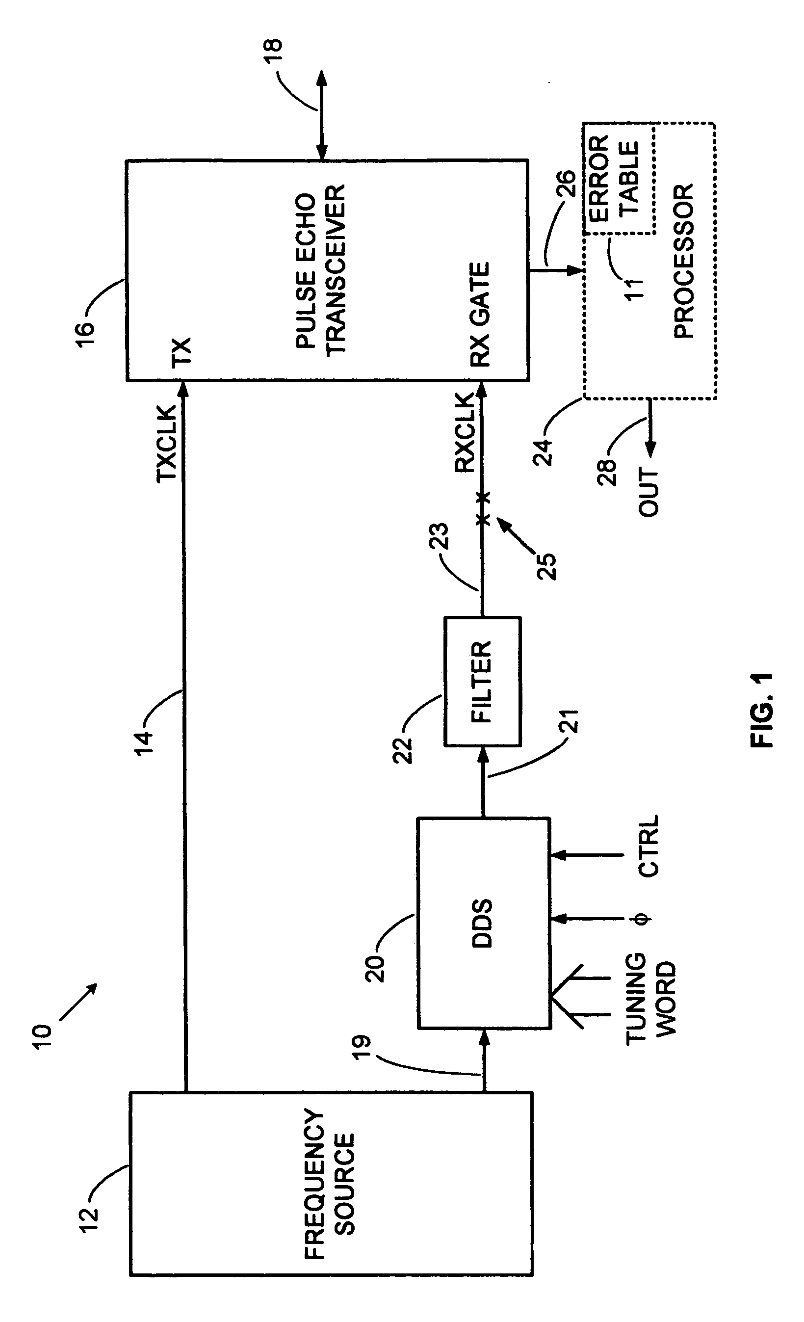
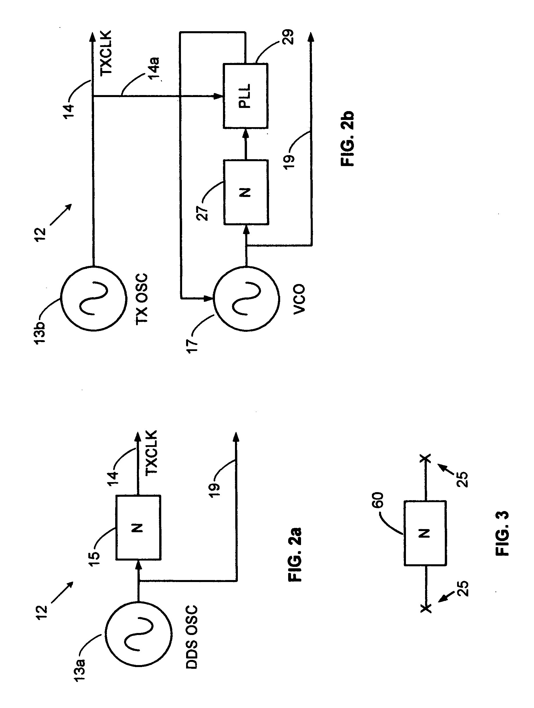
[0027] Direct digital synthesis (DDS) generates frequencies by digitally accumulating phase in a manner that directly emulates the definition of frequency. Frequency ω can be defined by a rate of change in phase φ or 107 =φ / t, where t is time. This can readily be seen from the well-known relation φ=ωt. As time progresses, phase continually increases. Direct digital synthesis emulates this process by continually incrementing a digital phase value in discrete phase increments in a phase accumulator. It performs the accumulation in discrete time steps. The size of the discrete phase increment is set by a digi...


PUM


Abstract

A direct digital synthesizer (DDS) drives a receive sampling gate at a frequency that is offset from a transmit pulse frequency to produce an expanded time sampled echo signal. The frequency offset generates a smoothly slipping phase between realtime received echoes and the sampling gate that stroboscopically expands the apparent time of the sampled echoes with an exemplary factor of 1-million and a range accuracy of 1-centimeter. The flexibility and repeatability of the digitally synthesized timing system is a quantum leap over analog prior art. The rock solid stability of the DDS allows further accuracy improvement via an error correction table.

Description

BACKGROUND OF THE INVENTION [0001] 1. Field of the Invention [0002] The present invention relates to radar timing circuits and more particularly to precision swept delay circuits for expanded time ranging systems. It can be used to generate a swept-delay dock for sampling radar, Time Domain Reflectometry (TDR) and laser systems. [0003] 2. Description of Related Art [0004] High accuracy pulse-echo ranging systems, such as wideband and ultra-wideband pulsed radar, pulsed laser rangefinders, and time domain reflectometers, sweep a timing circuit across a range of delays. The timing circuit controls a receiver sampling gate such that when an echo signal coincides with the temporal location of the sampling gate, a sampled echo signal is obtained. The echo range is then determined from the timing circuit, so high timing accuracy is essential. A stroboscopic time expansion technique is employed, whereby the receiver sampling rate is set to a slightly lower rate than the transmit pulse rate...

Claims


Application Information

Patent Timeline
IPC IPC(8): G06F1/02
CPCG01S7/285G01S7/497G01S7/40G06F1/0335
Inventor MCEWAN, THOMAS EDWARD
Owner MCEWAN TECH
Why Eureka
Try Eureka