Gas leak detection device and method for same

Active Publication Date: 2007-08-23
TOYOTA JIDOSHA KK
View PDF5 Cites 35 Cited by
  • Summary
  • Abstract
  • Description
  • Claims
  • Application Information

AI Technical Summary

Benefits of technology

[0006] Accordingly, it is an object of the present invention to provide a gas leak detection device that can detect a gas leak from a main valve of a hydrogen supply source with a high accuracy according to the pressure state of a fuel gas supply channel.
[0011] In particular, in accordance with the present invention, in the depressurization treatment, the fuel gas supply channel is depressurized until the pressure enters a pressure range in which the pressure can be monitored in the pressure monitoring device or pressure sensor. Therefore, pressure conditions suitable for pressure detection are recognized and environmental setting can be made according to the characteristics of the pressure detection means. In particular, if a pressure range in the pressure monitoring device or pressure sensor enables the measurements in a comparatively low pressure range, highly accurate pressure detection is possible and a very small gas leak, such as in the main valve or shutdown valve, can be correctly detected.
[0017] Furthermore, a plurality of pressure monitoring device with different pressure ranges may be provided in the fuel gas supply range and one pressure monitoring device may be selected to monitor the pressure according to the level of the reduced pressure in the fuel gas supply channel. When pressure monitoring devices are provided correspondingly to the pressure range, e.g., for a high pressure and a low pressure, a pressure monitoring device is selected correspondingly to the pressure inside the gas supply channel after the depressurization, this device being capable of performing accurate detection at this pressure. Therefore, leak determination accuracy can be increased.
[0022] The shutdown valve and the main valve are preferably closed in the course of the depressurization treatment downstream of the shutdown valve. The shutdown valve and main valve, for example, have a pilot solenoid valve configuration, because with valves of such configuration, sealing can be reliably performed by the shutdown treatment, while reducing the downstream pressure.

Problems solved by technology

However, a pressure sensor has a range of pressure that can be measured, and a pressure sensor that can be used in a high pressure range generally has a wide range of pressure that can be measured, but the measurement accuracy thereof is low.
Therefore, when pressure detection is conducted without taking into account the state of pressure detection means that has such a characteristic, highly accurate leak detection is impossible.

Method used


Image

  • Gas leak detection device and method for same
  • Gas leak detection device and method for same
  • Gas leak detection device and method for same

Examples


embodiment 1

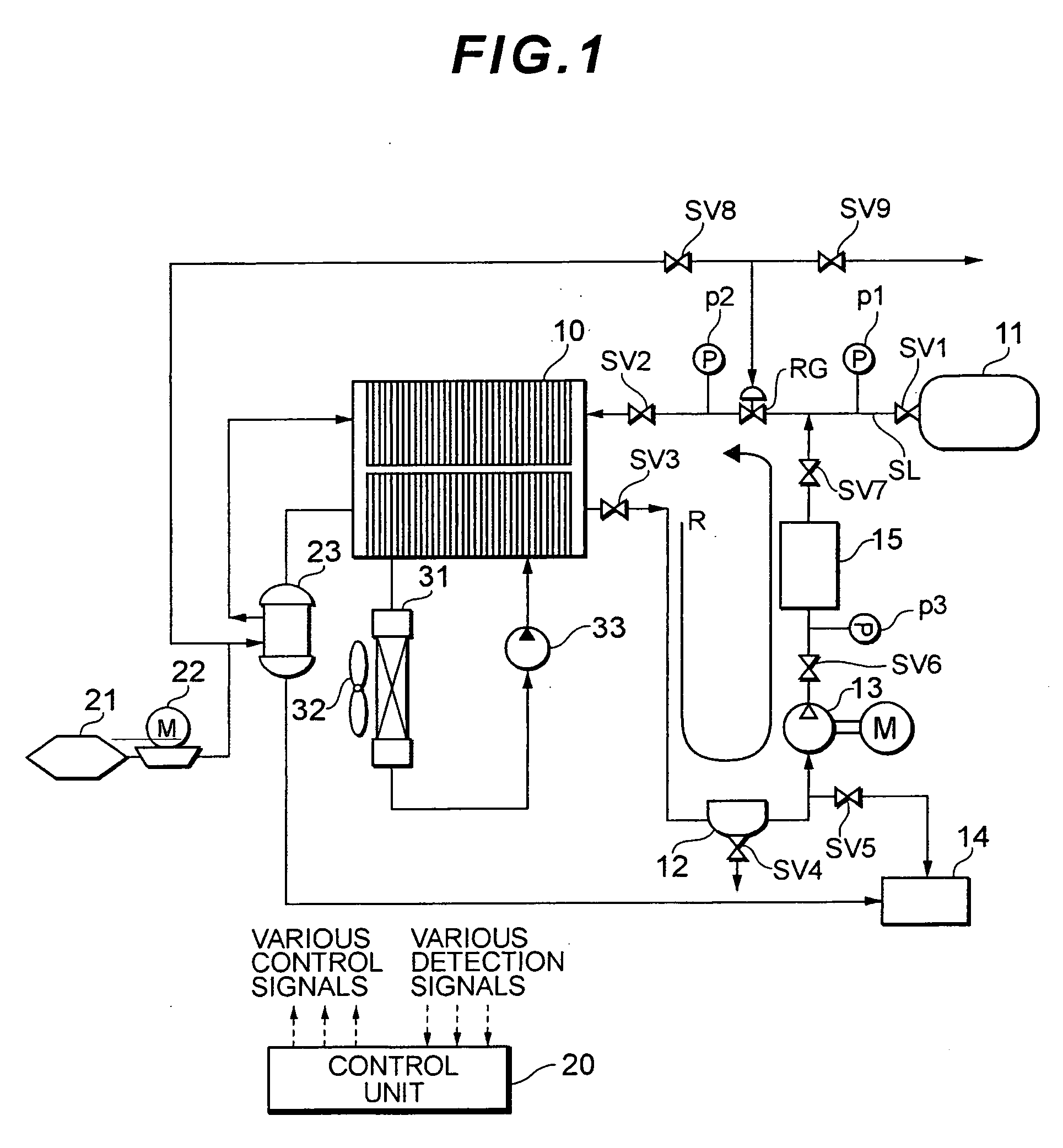
[0032] In Embodiment 1, the gas leak detection device in accordance with the present invention is employed in a fuel cell system installed on a mobile structure such as an electric automobile. FIG. 1 shows the present fuel cell system in its entirety.

[0033] As shown in FIG. 1, the fuel cell system comprises a system for supplying a hydrogen gas, which is a fuel gas, to a fuel cell stack 10, a system for supplying air, which is an oxygen source, and a system for cooling the fuel cell stack 10.

[0034] The fuel cell stack 10 has a stack structure having stacked therein a plurality of separators having channels for hydrogen gas, air, and cooling liquid and cells, each comprising a MEA (Membrane Electrode Assembly) sandwiched between a pair of separators. The MEA has a structure in which a polymer electrolyte membrane is sandwiched between two electrodes: a fuel electrode and an air electrode. In the fuel electrode, a catalyst layer for the fuel electrode is provided on a porous support...

embodiment 2

[0075] Embodiment 2 of the present invention relates to a structure in which the recovery tank of Embodiment 1 is provided at the main valve SV1. FIG. 5 is a system diagram of the entire fuel cell system of Embodiment 2.

[0076] As shown in FIG. 5, the fuel cell system of Embodiment 1 has a structure almost identical to that of the system of Embodiment 1, but the recovery tank 15 is provided in the vicinity of the main valve SV1.

[0077] In other words, the channel for supplying hydrogen gas to the recovery tank 15 is connected downstream of the main valve SV1, and a circulation route is provided which comprises a hydrogen pump 16, a shutdown valve SV10, a pressure sensor p4, a recovery tank 15, and a shutdown valve SV11. Furthermore, a return check valve RV is provided instead of the recovery tank 15 and circulation shutdown valve SV7 in the circulation route R. The point where the circulation route R is joined to the hydrogen gas supply channel is downstream of the pressure regulati...


PUM


Abstract

A gas leak detection device for a fuel cell system equipped with a main valve (SV1) in a fuel gas supply source (11), comprising a shutdown valve (SV2) provided in a fuel gas supply channel downstream of the main valve (SV1), pressure monitoring devices (p1, p2, 20) for monitoring a pressure in the fuel gas supply channel between the main valve and the shutdown valve, a depressurization treatment devices (10, 15, SV5) for depressurizing the inside of the fuel gas supply channel, and a determination device (20) for monitoring a variation of pressure in a sealed space of the fuel gas supply channel formed between the main valve and the shutdown valve after the main valve and the shutdown valve have been closed and determining the operation state of the main valve based on the variation of pressure in the sealed space. In the depressurization treatment, the fuel gas supply channel is depressurized until the pressure enters a pressure range in which the pressure can be monitored in the pressure monitoring device.

Description

TECHNICAL FIELD [0001] The present invention relates to a fuel cell system, and more particularly to a technology for detecting a gas leak from a main valve of a hydrogen tank. BACKGROUND ART [0002] A technology has been developed for detecting leak of hydrogen gas, which is a fuel gas, in the conventional fuel cell systems. For example, as described in Japanese Patent Application Laid-open No. 2002-151126, a pressure of a hydrogen tank is detected to detect an amount of hydrogen gas used, the current amount of hydrogen gas used is estimated from the past driving history, and gas leak is detected based on the detected amount of hydrogen gas used and the estimated amount of hydrogen gas used. [0003] Japanese Patent Application Laid-open No. 2003-308868 disclosed an invention according to which a pressure drop ratio is calculated based on an elapsed time and pressure information from a pressure sensor after closing a shutdown valve, and the shutdown valve is considered to be in a dama...

Claims


Application Information

Patent Timeline
IPC IPC(8): G01M3/28H01M8/04H01M8/10
CPCY02E60/50H01M8/04231
Inventor YOSHIDA, NAOHIRO
Owner TOYOTA JIDOSHA KK
Why Eureka
Try Eureka