Supercharger drive pulley

a technology of supercharger and drive pulley, which is applied in the direction of interengaging clutches, couplings, slip couplings, etc., can solve the problems of high reverse load on the belt, damage or break of components, undetectable loads, etc., and achieve the effect of reducing peak loads, reducing damage to the supercharger, and increasing the life of such components

Active Publication Date: 2007-08-23
ATI PERFORMANCE PRODS
View PDF8 Cites 13 Cited by
  • Summary
  • Abstract
  • Description
  • Claims
  • Application Information

AI Technical Summary

Benefits of technology

[0006] The present invention is a supercharger drive pulley that includes a one way drive clutch and a supercharger system that incorporates such a supercharger drive pulley. The one way drive clutch provides for a direct driving of the supercharger but also allows the supercharger to freewheel and overrun the crankshaft in situations where the supercharger rpm is correspondingly higher than the crankshaft rpm, such as the above-described very rapid full throttle / high rpm to closed throttle transitions. This decreases peak loads on the supercharger and supercharger drive system in general, and in particular, on the drive belt, thereby reducing damage to the supercharger and supercharger drive system and breakage of drive belts, increasing the life of such components, as well as potentially reducing operating costs. The present invention can also prevent supercharger and / or supercharger drive system failure that can disable the vehicle, especially at an undesired time and / or prior to the completion of a race or other performance event.

Problems solved by technology

This situation can create a very high reverse load on the belt, which can stretch, damage or even break the belt or cause other damage to the supercharger or supercharger drive system.
Undesired loads, which damage or break components, or reduce their operating life, can also be caused even in more moderate situations which are not at the extremes of high output engines and / or very rapid full throttle / high rpm to closed throttle transitions.
This can reduce loads on the supercharger and drive system and reduce belt breakage but this belt slippage also limits supercharger boost and thus, engine power.
Many race cars use a 14 mm toothed belt to stop belt breakage but the use of such a belt over a standard 8 mm belt can absorb as much as 100 horsepower in a race engine, reducing total power output of the engine.

Method used


Image

  • Supercharger drive pulley
  • Supercharger drive pulley
  • Supercharger drive pulley

Examples


Embodiment Construction

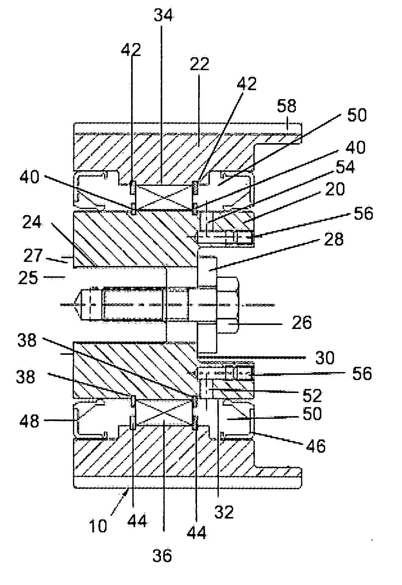
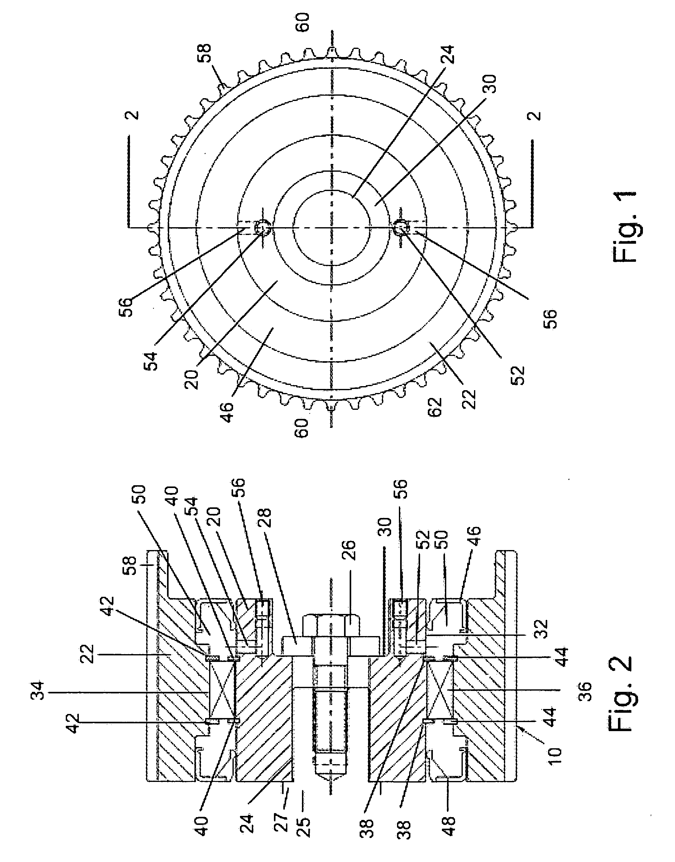
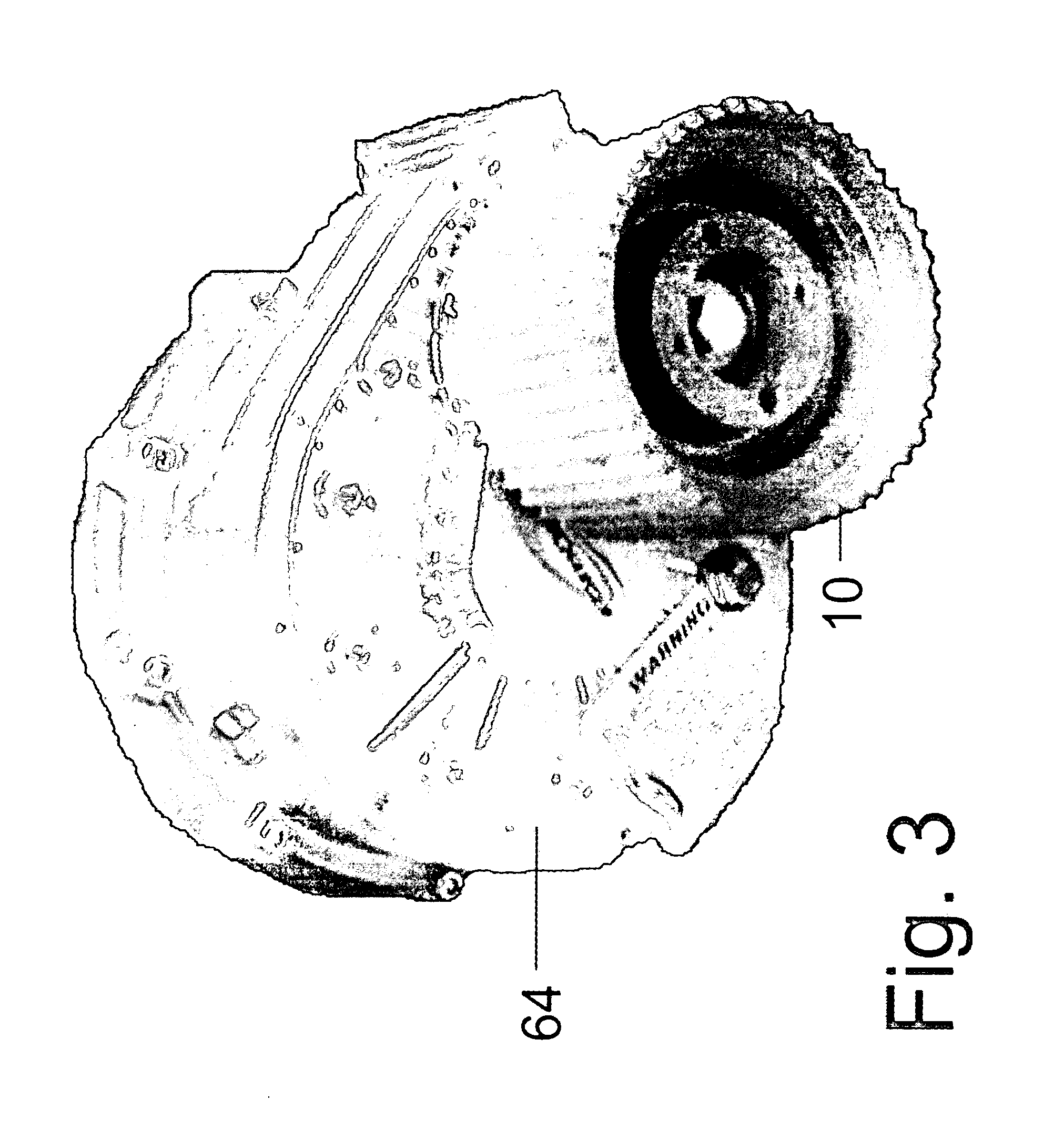
[0023] The supercharger drive pulley 10 of the present invention includes an inner hub 20 and an outer drive pulley 22. The inner hub 20 includes an inner axial bore 24 sized to be positioned on an end of a drive shaft 25 of a supercharger 64 (FIG. 3) with a desired fit so as to drive the drive shaft 25 of the supercharger 64, and thus, drive the supercharger 64. The inner bore 24 can be slotted for a woodruff or other type of key, can be tapered for fitting on a tapered end of a shaft, or can be splined for fitting on a splined end of a shaft. Other hub / shaft fixing mechanisms can also be used. In the presently preferred embodiment, the drive shaft 25 includes two woodruff slots positioned 180° apart on the shaft 25 to accept two woodruff keys that engage two corresponding slots 62 positioned on the inner bore 24. A bolt 26 or other type of threaded fastener engages a threaded bore in the supercharger drive shaft 25 to retain the drive pulley 10 on the shaft. A washer 28 is prefera...


PUM


Abstract

A supercharger drive pulley includes an inner hub and an outer drive pulley. One of the inner hub and the outer drive pulley is drivingly connected to a drive shaft of a supercharger for driving the supercharger and the other of the inner hub and the outer drive pulley is drivingly connected to an engine for being driven by the engine. A one way drive clutch is drivingly engaged between the inner hub and the outer pulley to allow driving torque from the engine to be transmitted to the supercharger in one direction and to allow the supercharger to freewheel in conditions where it overruns the engine.

Description

[0001] This application claims priority to U.S. Provisional Patent Application No. 60 / 727,873, filed Oct. 19, 2005, entitled “Supercharger Drive Pulley” and to U.S. Provisional Patent Application No. 60 / 762,865, filed Jan. 30, 2006, entitled “Supercharger Drive Pulley”, both of which applications are incorporated by reference herein.BACKGROUND OF THE INVENTION [0002] The present invention relates to internal combustion engine superchargers. [0003] Superchargers are frequently used on internal combustion piston engines to increase power of the engine. They are positively driven compressors used to pump air into the cylinders of the engine. The increase mass of oxygen forced into the cylinders by the supercharger allows the engine to burn more fuel, improving the volumetric efficiency and power of the engine. Superchargers are typically of a Roots (lobe) type, Eaton (twin screw) type or centrifugal type. Modern automotive superchargers are typically driven by a toothed belt from a too...

Claims


Application Information

Patent Timeline
Patent Type & Authority Applications(United States)
IPC IPC(8): F02B33/00F16D11/00F16D43/20
CPCF02B33/34F02B39/12F02B39/02
Inventor BEATTIE, JAMES C.
Owner ATI PERFORMANCE PRODS
Why Eureka
Try Eureka