Valve Device

a valve and valve body technology, applied in the direction of valve operating means/release devices, non-mechanical valves, machines/engines, etc., can solve the problem of possible failure of the egr valve operation, and achieve the effect of simplifying processing and structur

Active Publication Date: 2007-08-23
KOMATSU LTD
View PDF9 Cites 27 Cited by
  • Summary
  • Abstract
  • Description
  • Claims
  • Application Information

AI Technical Summary

Benefits of technology

[0014] Second, in the EGR valve device disclosed in Patent Document 2, since the solenoid valve 133 is provided separately from the housing 112, the oil sending line 132 for sending the pressured oil to the solenoid valve 133 and to the housing 112 is needed, so that the number of components is increased. Also, since the solenoid valve 133 is provided separately from the housing 112, the space for installing the EGR valve device is increased.
[0044] With such arrangement, although the cooling oil can only be jetted while the EGR valve device is working, since the nozzle is provided very close to the hydraulic circuit for driving the hydraulic actuator, processing and structure can be simplified.

Problems solved by technology

Further, in the exhaust gas having reduced temperature, since sulfuric acid will be generated from the sulfur content in fuel, corrosion by the sulfuric acid will occur, and the carbon will further deposit on the corroded part to cause the fixing, so that operation failure of the EGR valve will possibly occur.

Method used


Image

  • Valve Device
  • Valve Device
  • Valve Device

Examples


Embodiment Construction

[0058] Preferred embodiments of the present invention are described below referring to the accompanying drawings.

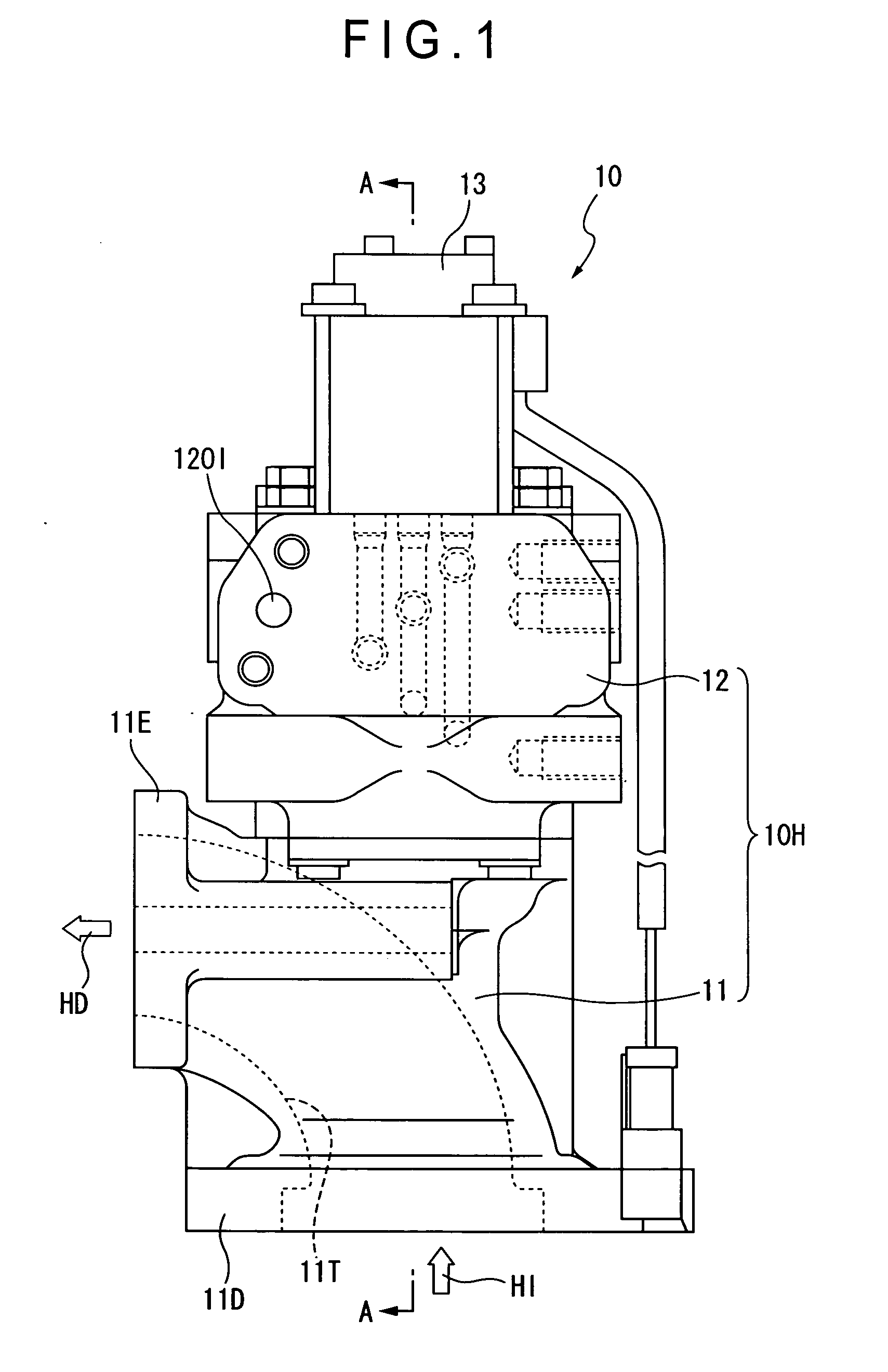
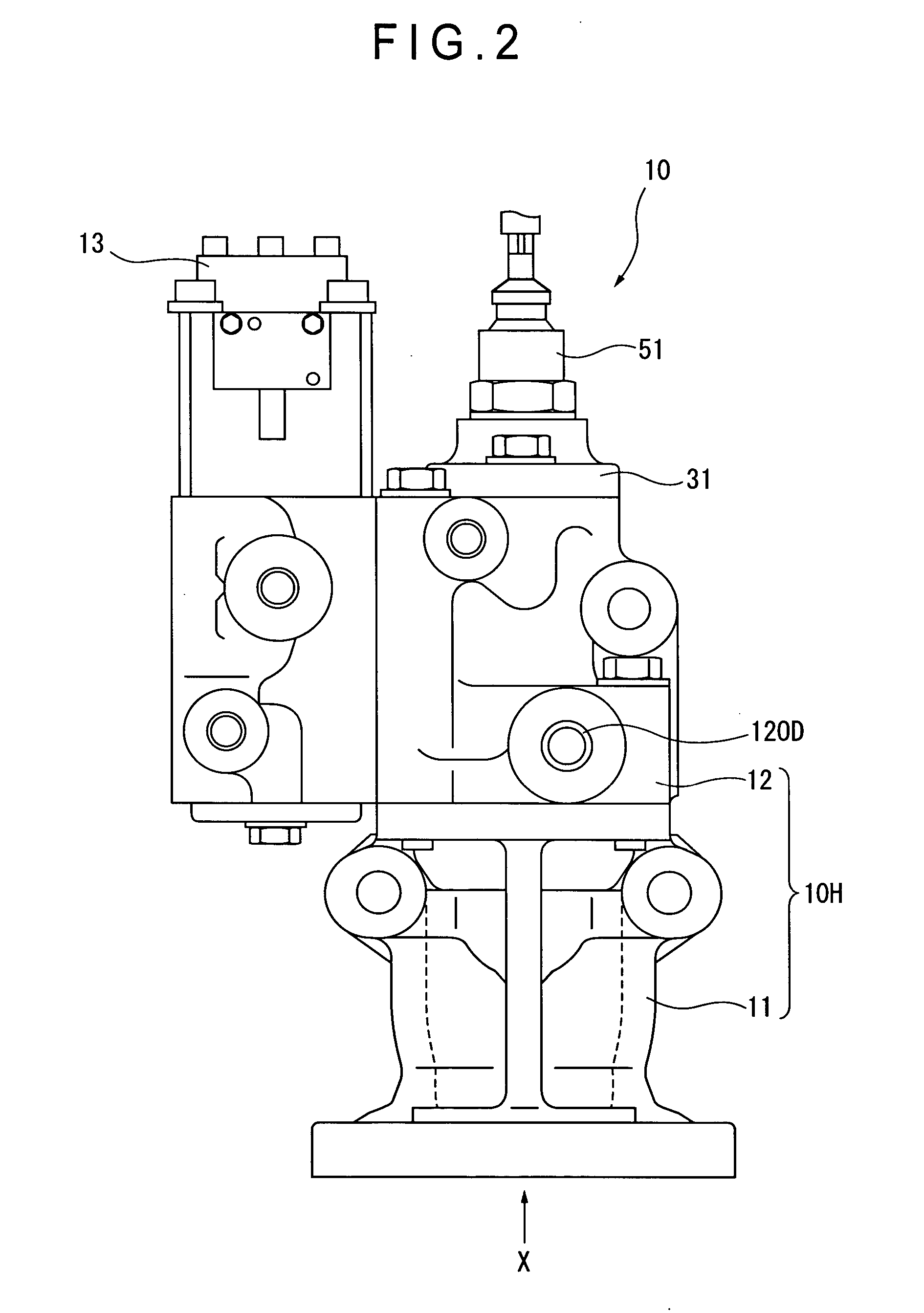
[0059]FIG. 1 is a front elevational view showing a valve device according to the present invention, and FIG. 2 is a right side view of the same. FIG. 3 is a cross section taken along A-A line of FIG. 1. FIG. 4 is a bottom view viewed from the X-direction of FIG. 2.

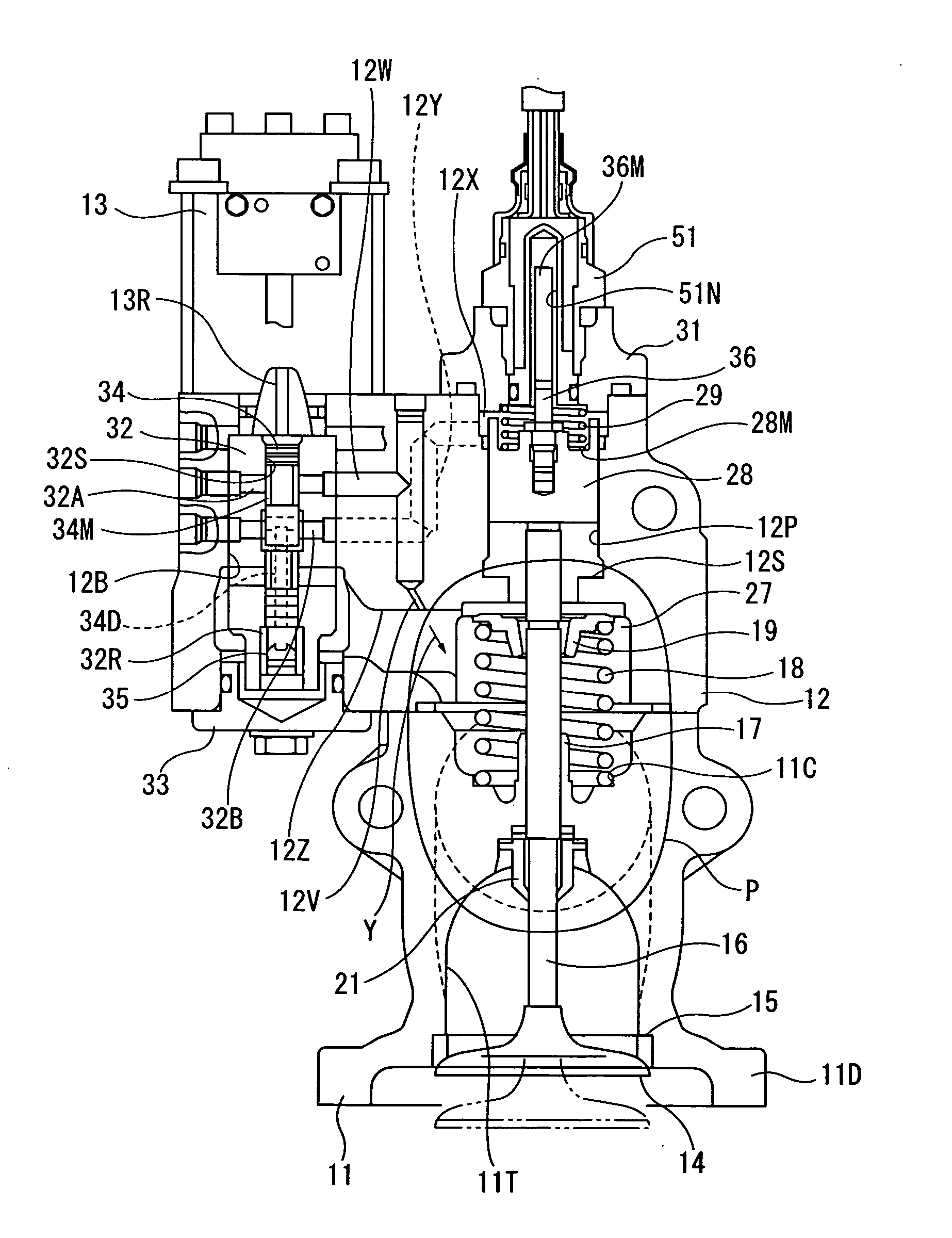
[0060] As shown in FIG. 1 and FIG. 2, an EGR valve device 10 (which is the valve device of the present invention) has a housing 11, a case 12, a solenoid 13, and a position sensor 51. A valve housing body 10H is formed by the housing 11 and the case 12 which is mounted on the upper surface of the housing 11 by bolts.

[0061] As shown in FIG. 4, the valve housing body 10H is separated into two parts of the housing 11 (which is a valve section) and the case 12 (which is a drive section), and, by providing bolt holes and screw holes on the circumference centering the axis of a valve 14 at an angular interval of 90...


PUM


Abstract

A valve device includes a valve housing body having a passage for fluid, a valve guide formed in the valve housing body, a valve stem sliding in the valve guide for opening and closing the valve, a hydraulic actuator for opening and closing a valve, and a hydraulic control valve for controlling the hydraulic actuator, in which a scraper is provided on an end of the passage side of the valve guide for scraping the deposits on the valve stem. Further, the hydraulic actuator and the hydraulic control valve are integrated with the valve housing body. Furthermore, the device is provided with a nozzle oriented toward the valve guide and having an orifice for jetting pressured oil for cooling.

Description

TECHNICAL FIELD [0001] The invention relates to a valve device, and more particularly to a valve device suitable to be used for performing EGR. BACKGROUND ART [0002] As a measure to reduce the nitrogen oxides (NOx) contained in the exhaust gas of a diesel engine, there is conventionally known an EGR valve device, which is an exhaust gas passage valve, for performing so called EGR (Exhaust Gas Recirculation) in which a part of the exhaust gas generated by the engine is returned to the intake system of the engine for recirculation (refer to, for example, Patent Document 1 and Patent Document 2). [0003] EGR valve is not only exposed to the high temperature exhaust gas introduced from exhaust pipe, but also exposed to the exhaust gas cooled by a recirculation exhaust gas cooler and therefore having reduced temperature. Fine particles such as carbon exist in the exhaust gas, and the carbon will deposit on the valve stem of the EGR valve. Further, in the exhaust gas having reduced tempera...

Claims


Application Information

Patent Timeline
Patent Type & Authority Applications(United States)
IPC IPC(8): F16K31/02F16K1/00F02M25/07F02B47/08F01L3/08F01L3/24F01L9/10F01L9/16F01L9/20F01L9/22F16K1/32F16K29/00F16K49/00F16K51/00
CPCF01L3/08Y02T10/121F01L9/02F01L9/026F01L9/04F01L2009/0411F01L2101/00F01L2800/10F01L2820/01F02M25/0701F02M25/0737F02M25/0779F02M25/0789F02M25/0795F02M25/0797F16K29/00F01L3/24F02M26/59F02M26/73F02M26/74F02M26/50F02M26/32F02M26/67F01L2301/00F01L9/16F01L9/22F01L9/10F01L9/20F16K51/00F16K49/00F16K1/32
Inventor SEIYAMA, HIDEYUKIOKUBO, TAISEIOKAYA, KOUICHIIWAZAKI, TATSUYATSUDA, HIROSHI
Owner KOMATSU LTD
Why Eureka
Try Eureka