
Method for making a blood pump and pumping blood

Inactive Publication Date: 2007-08-23
PALMER ARTHUR
View PDF19 Cites 12 Cited by
  • Summary
  • Abstract
  • Description
  • Claims
  • Application Information

AI Technical Summary

Benefits of technology

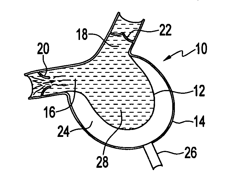
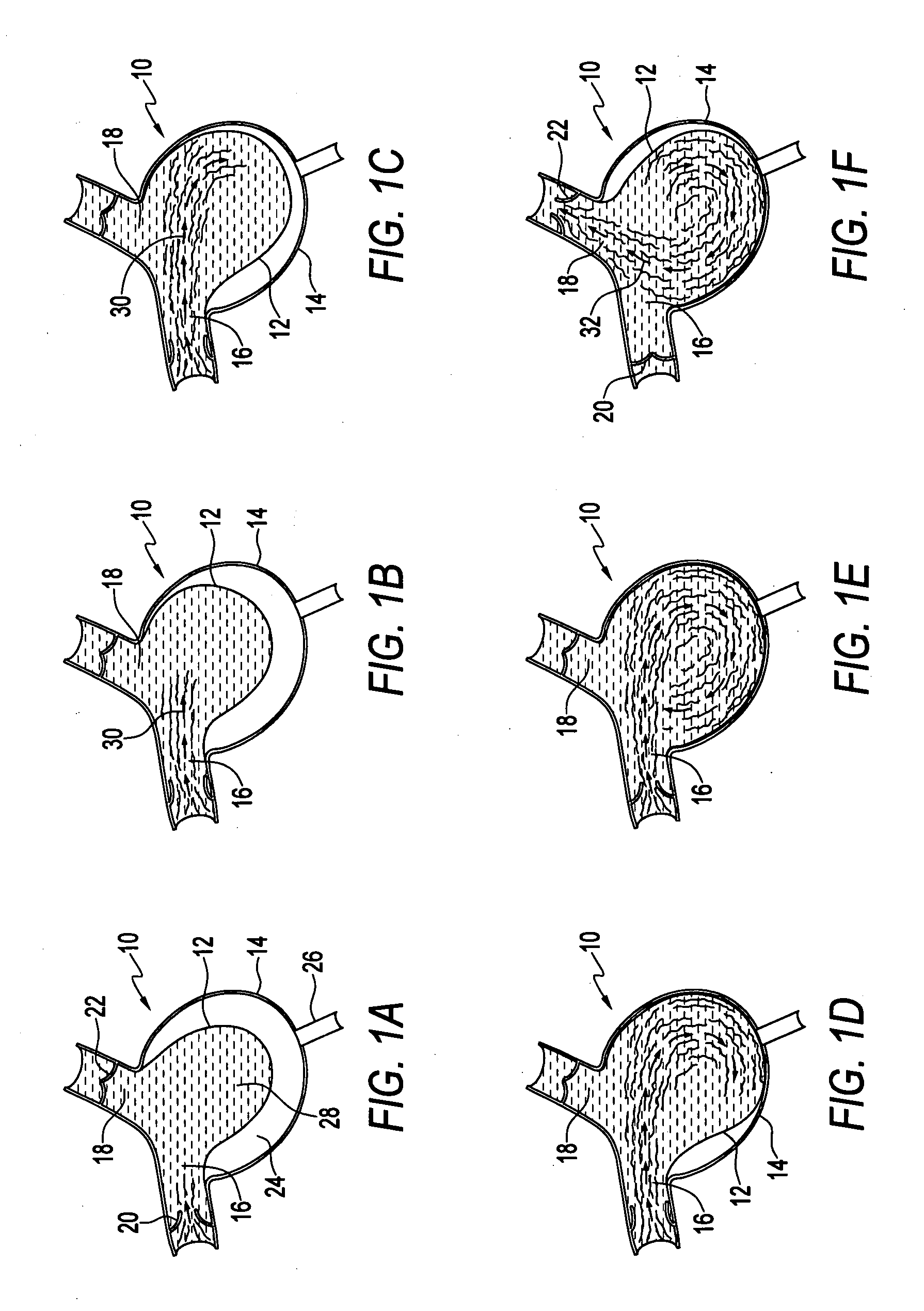
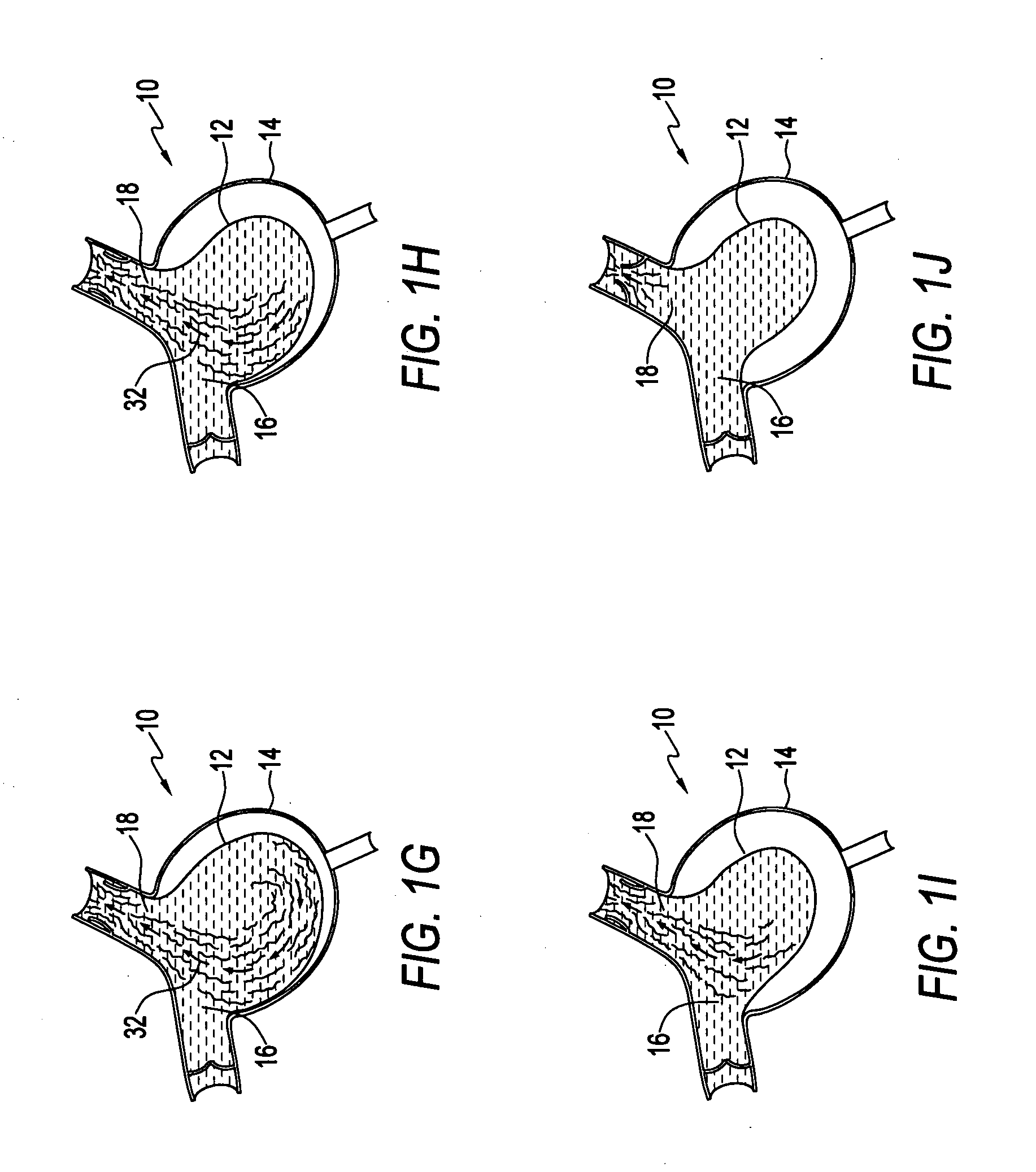
[0008] One aspect of the present invention is to guide and direct the flow of blood through the pumping chamber by reason of the action of an expansile bladder on the blood flow. A continuous circular or spiral fluid path is obtained that more effectively washes the inlet and discharge ports as well as the walls of the pumping chamber with the pumped fluid, i.e., blood. Control of fluid shear and good washing of all areas of the bladder will decrease the tendency for blood clotting. The blood is initially drawn into the pumping chamber through the inlet port. As the blood flows into the pumping chamber it washes the discharge port. As various areas of the bladder sequentially expand and contract, the blood is guided through the pumping chamber washing the chamber walls. Prior to being ejected out of the discharge port, the blood washes past the inlet port. It is expected that the flow of blood directed across the inlet and discharge ports and the washing action associated with this flow will decrease clotting in these areas. Also, by appropriately directing the flow of the blood through the device and optimizing the angle of the inlet and the discharge port, the inertia of the blood will contribute to the action of the bladder and the path of the blood flow through the device. A smoother laminar flow through the pumping chamber afforded by the expansible bladder will improve the efficiency of the pump and decrease energy requirements.
[0009] One of the important initiators of blood clotting is the platelet. Platelets are formed elements that are manufactured in the bone marrow and circulate in the bloodstream along with red cells, white cells and other formed elements. Platelets normally circulate in an inactivated state. There are many diverse stimuli that can activate platelets causing them to adhere to surfaces, to aggregate and initiate clotting. One of these stimuli is the level of shear. Areas of high shear may activate platelets then if the activated platelets flow through a region of low shear, or slow flow, they may begin to form a clot. Control of shear stress by controlling parameters of flow, such as local velocity is very important in artificial blood pumps. The embodiments of the present invention provide more control over local velocity than previously available designs.
[0014] The bladder and pump operating system design are then tested, preferably by generating a computer model of the apparatus and generating simulated fluid flow using the same mathematical techniques described above, but now in the sequence of having a given pump design and generating the flow pattern therefrom. Problems in bladder and operating system design may mandate reversion back to previous steps with further modification of the size or shape of the housing, or shape or composition of the bladder, or means for driving the bladder. More than one simultaneous flow pathway through the bladder may be required. A prototype will be constructed based on the computer model. This will be bench tested followed by animal and human testing. Further refinement of the shell and bladder design will be made following prototype testing to simulate flow in natural hearts, eliminate stagnation points, provide laminar flow, wash ports, conserve energy, and reduce the potential for thrombosis.

Problems solved by technology

Aside from redesign of the geometry of the device, they have little or no ability to guide the flow of fluid through the pumping chamber.
Flow momentum is lost, and considerable turbulence is created.

Method used


Image

  • Method for making a blood pump and pumping blood
  • Method for making a blood pump and pumping blood
  • Method for making a blood pump and pumping blood

Examples


Embodiment Construction

[0017] The following is a detailed description of certain embodiments of the invention presently deemed by the inventor to be the best mode of carrying out his invention. The invention as defined by the appended claims is not limited to these embodiments, and additional embodiments of the claimed inventive concept will undoubtedly be apparent to those skilled in the art.

[0018] Referring to the drawings, FIGS. 1A-1F illustrate a pump apparatus 10 constructed generally in accordance with my earlier patent, U.S. Pat. No. 6,579,223. Pump 10 comprises an expansile bladder 12 within a shell or housing 14. The bladder and housing in this embodiment are generally round and in only two dimensions for ease in illustrating the concept, and may be easier to begin with in the initial designs. Nevertheless, other shapes can be used and may be preferable, such as conical or heart-shaped bladders and the actual designs will be in three dimensions. The bladder has an inlet port 16 and a discharge p...


PUM


Abstract

A method of making a blood pump comprises selecting a desired flow pattern in a pumping chamber defined by an extensible bladder wherein the flow pattern is based generally on blood flow in a natural heart, using an initial computer model of the desired flow pattern to determine the material composition and dynamic operation conditions of each portion of the bladder, designing a bladder and pump operating system, computer modeling the actual design, testing and refining the design, and constructing a prototype based thereon. The desired flow pattern includes guiding and directing the flow of blood through the pumping chamber by reason of the action of an expansile bladder on the blood flow. A continuous circular or spiral fluid path is obtained that more effectively washes all areas of the bladder including the inlet and discharge ports with blood to reduce thrombosis.

Description

REFERENCE [0001] This application is a continuation-in-part of co-pending International PCT Application No. PCT / US2005 / 038635, filed Oct. 25, 2005, designating the United States, and claiming priority from U.S. Provisional Patent Application Ser. No. 60 / 621,920 filed Oct. 25, 2004, which applications are hereby incorporated by reference.TECHNICAL FIELD [0002] The subject application relates generally to fluid pumps, and more particularly to blood pumps, cardiac assist devices, methods for making blood pumps and blood pumping methods. BACKGROUND ART [0003] The natural heart functions in a fashion similar to a positive displacement pump. Each of the two pumping chambers in the natural heart has two check valves (an inlet and an outlet valve). The walls of the natural heart are made of contractile muscle that provide the power to pump the blood. Each pumping cycle consists of a filling or diastolic phase of the pumping cycle and an ejection or systolic phase of the pumping cycle. Durin...

Claims


Application Information

Patent Timeline
IPC IPC(8): A61M1/12A61M60/196A61M60/268A61M60/43A61M60/562A61M60/837A61M60/894G16Z99/00
CPCA61M1/1037A61M1/106A61M1/122G06F19/3437G06F2217/16G06F17/5009A61M2205/3334G16H50/50G06F2111/10G06F30/20A61M60/896A61M60/148G16Z99/00A61M60/43A61M60/562A61M60/196A61M60/894A61M60/837
Inventor PALMER, ARTHUR
Owner PALMER ARTHUR
Learn More