Internal combustion engine

a combustion engine and combustion chamber technology, applied in the direction of engine starters, combustion air/fuel air treatment, muscle operated starters, etc., can solve the problems of increasing fuel consumption, spark plug soot, and inability to say favorable diffusion of fuel-air mixture in the combustion chamber

Inactive Publication Date: 2007-08-30
HONDA MOTOR CO LTD
View PDF8 Cites 7 Cited by
  • Summary
  • Abstract
  • Description
  • Claims
  • Application Information

AI Technical Summary

Benefits of technology

[0008]The first aspect of the present invention has been made in consideration of the above circumstances. Accordingly, it is an object of the present invention to provide an internal combustion engine in which the blow-by of an unburned fuel-air mixture and the problem that the spark plug becomes sooty can be restrained.

Problems solved by technology

Therefore, in the case of performing an operation in which the intake gas charging effect is enhanced by overlapping a part of the intake valve opening period with a part of the exhaust valve opening period, part of the fuel-air mixture would blow by through the exhaust valve port in an unburned state, thereby increasing the fuel consumption, and it would be necessary to after-treat the unburned fuel-air mixture.
In addition, where a tip end portion of the spark plug is disposed to face the intake valve port, there would be a problem (particularly, at the time of warming up) in that the spark plug becomes sooty.
However, in the internal combustion engine disclosed in Japanese Patent No. 2537205, a fuel-air mixture flows skewly into the combustion chamber via the intake valve port when the intake valve is opened, so that diffusion of the fuel-air mixture in the combustion chamber cannot be said to be favorable, and the combustion efficiency also cannot be said to be sufficient.

Method used


Image

  • Internal combustion engine
  • Internal combustion engine
  • Internal combustion engine

Examples


first embodiment

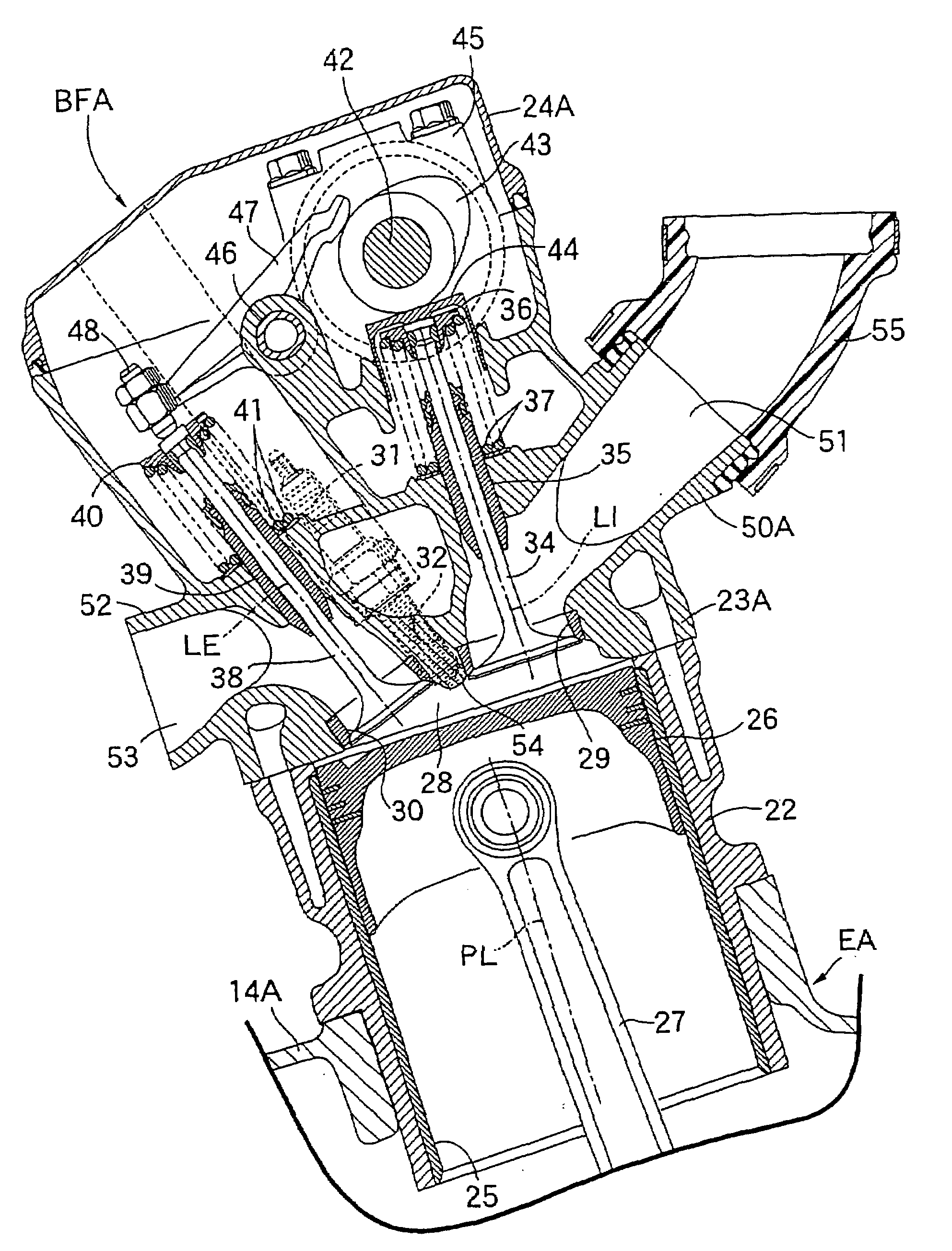
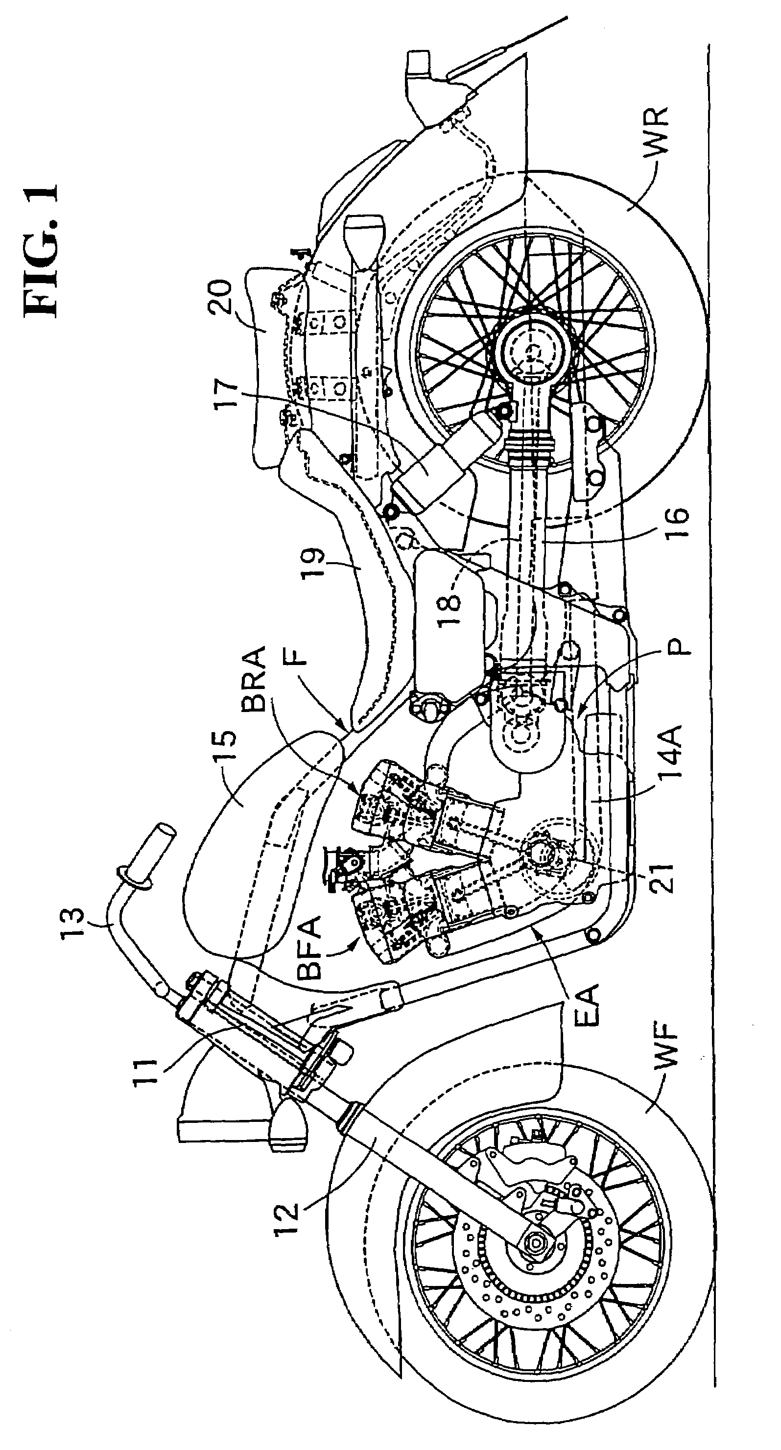
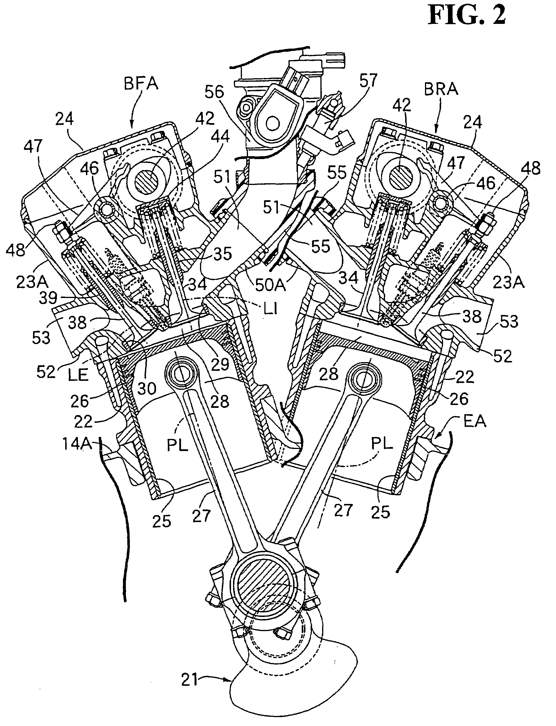
[0033]FIGS. 1 to 3 show the present invention, in which FIG. 1 is a side view of a motorcycle, FIG. 2 is a vertical sectional side view of an essential part of an internal combustion engine, and FIG. 3 is an enlarged view of an essential part of FIG. 1.

[0034]First, in FIG. 1, a front fork 12 for rotatably supporting a front wheel WF is steerably borne on a head pipe 11 provided at the front end of a vehicle body frame F of the motorcycle. A steering handle 13 is connected to the front fork 12. In addition, a power unit P composed of an internal combustion engine EA and a transmission (not shown) contained in a crankcase 14A possessed by the internal combustion engine EA is mounted on a front portion of the vehicle body frame F. A fuel tank 15 is mounted on a front portion of the vehicle body frame F so as to cover the upper side of the internal combustion engine EA.

[0035]The front ends of a left-right pair of swing arms 16 extending in the front-rear direction are vertically swingab...

second embodiment

[0063]In the second embodiment, throttle bodies 56, 56 in the banks BFB and BRB extend in the up-down directions so that they do not overlap with each other as viewed in the direction along the axis of the crankshaft 21, and the throttle bodies 56 are connected to the connecting pipe portions 50B through insulators 58, respectively.

[0064]Even in the case where the angle between the banks BFB and BRB must be set comparatively large, by disposing the throttle bodies 56, 56 so as not to overlap with each other as viewed in the direction along the axis of the crankshaft 21, as in the second embodiment, the one-side surfaces of the cylinder heads 23A, in which the intake ports 51 open continuous with the intake valve ports 29, are formed to be substantially parallel to the axes of the cylinder bores 25. Therefore, the side surfaces of the cylinder heads 23B on the sides where the intake ports 51 are provided can be set at positions close to the axes of the cylinder bores 25, whereby the ...

third embodiment

[0070]In the third embodiment, an air cleaner 60 is disposed between both the banks BFC and BRC. Throttle bodies 56, 56 disposed substantially horizontally on the lower side of the air cleaner 60 are connected to the connecting pipe portions 50C through insulators 61, respectively. Connecting pipes 59 that extend upward from the throttle bodies 56 are connected in common to the air cleaner 60.

[0071]Even in the case where the angle formed between both the banks BFC and BRC must be set comparatively large, by disposing the air cleaner 60 between both the banks BFC and BRC as in the third embodiment, the one-side surfaces of the cylinder heads 23A, in which intake ports 51 open continuous with the intake valve ports 29, are formed to be substantially parallel to the axes of the cylinder bores 25. Therefore, side surfaces of the cylinder heads 23C on the sides where the intake ports 51 are provided can be set close to the axes of the cylinder bores 25, and the bulging of the cylinder he...


PUM


Abstract

In an internal combustion engine includes an intake valve port that opens into a combustion chamber on one side of a plane containing the axis of a cylinder bore. An exhaust valve port opens into the combustion chamber on the other side of the plane. A spark plug has a tip end that fronts a substantially central portion of the combustion chamber. The spark plug is disposed between the intake valve and the exhaust valve. In order to restrain the blow-by of an unburned fuel-air mixture, and to suppress the bulging of the cylinder head to the intake system side, the operation axis of an intake valve is set to be substantially parallel to the axis of the cylinder bore. In addition, one side surface of a cylinder head is formed to be substantially parallel to the axis of the cylinder bore.

Description

CROSS-REFERENCE TO RELATED APPLICATIONS[0001]This nonprovisional application claims priority under 35 U.S.C. § 119(a) on Patent Application Nos. 2006-052863 and 2006-052864, each filed in Japan on Feb. 28, 2006. The entirety of each of these applications is incorporated herein by reference.1. FIELD OF THE INVENTION[0002]A first aspect of the present invention relates to an internal combustion engine that includes a piston slidably fitted in a cylinder bore. A combustion chamber is formed between a cylinder block and a cylinder head, a top portion of the piston fronting on the combustion chamber. An intake valve port is opened and closed by an intake valve, the intake valve port being provided in the cylinder head in the state of opening into the combustion chamber on one side of a plane containing the axis of the cylinder bore. An exhaust valve port is opened and closed by an exhaust valve, the exhaust valve port being provided in the cylinder head in the state of opening into the c...

Claims


Application Information

Patent Timeline
Patent Type & Authority Applications(United States)
IPC IPC(8): F02B15/00F02M35/10F02N3/00
CPCF01L1/143F01L1/181F01L1/20F01L2001/0535F02M35/162F02B61/02F02M35/10104F02M35/10216F02M35/116F01L2003/255
Inventor INUI, HIROATSU
Owner HONDA MOTOR CO LTD
Why Eureka
Try Eureka