Non-Inductive Winding Wire-Type Solenoid Bobbin

a solenoid bobbin and non-inductive winding technology, which is applied in the direction of superconducting magnets/coils, emergency protective arrangements for limiting excess voltage/current, magnetic bodies, etc., can solve the problems of power outages, cutting the supply of electricity, and inner wire damage, etc., and achieves the effect of convenient flow

Inactive Publication Date: 2007-08-30
IND ACADEMIC CORP FOUND YONSEI UNIV
View PDF3 Cites 12 Cited by
  • Summary
  • Abstract
  • Description
  • Claims
  • Application Information

AI Technical Summary

Benefits of technology

[0020]Connection channels according to the present invention are provided on one side of each winding groove at regular intervals, thus serving as a passage for cooling the inner wire wound in the winding groove. The size of each connection channel is smaller than the width of the winding groo

Problems solved by technology

Such present fault current limiters lead to power outages by completely cutting the supply of electricity.
When an electrical power system experiences trouble, the limiter generates resistance accompanied by heat generation which is caused by a phase transition for limiting the fault current.
A conventional non-inductive winding wire-type solenoid bobbin is problematic in that no device is provided to mitigate the difference in cooling condition between an outer wire and an inner wire, so that the inner wire may be damaged by the heat when an excessive voltage is applied.
A conduction-cooling-type superconduc

Method used


Image

  • Non-Inductive Winding Wire-Type Solenoid Bobbin
  • Non-Inductive Winding Wire-Type Solenoid Bobbin
  • Non-Inductive Winding Wire-Type Solenoid Bobbin

Examples


Embodiment Construction

[0026]Hereinafter, the present invention will be described in detail with reference to the accompanying drawings. It is to be understood that the present embodiment is illustrative and not restrictive.

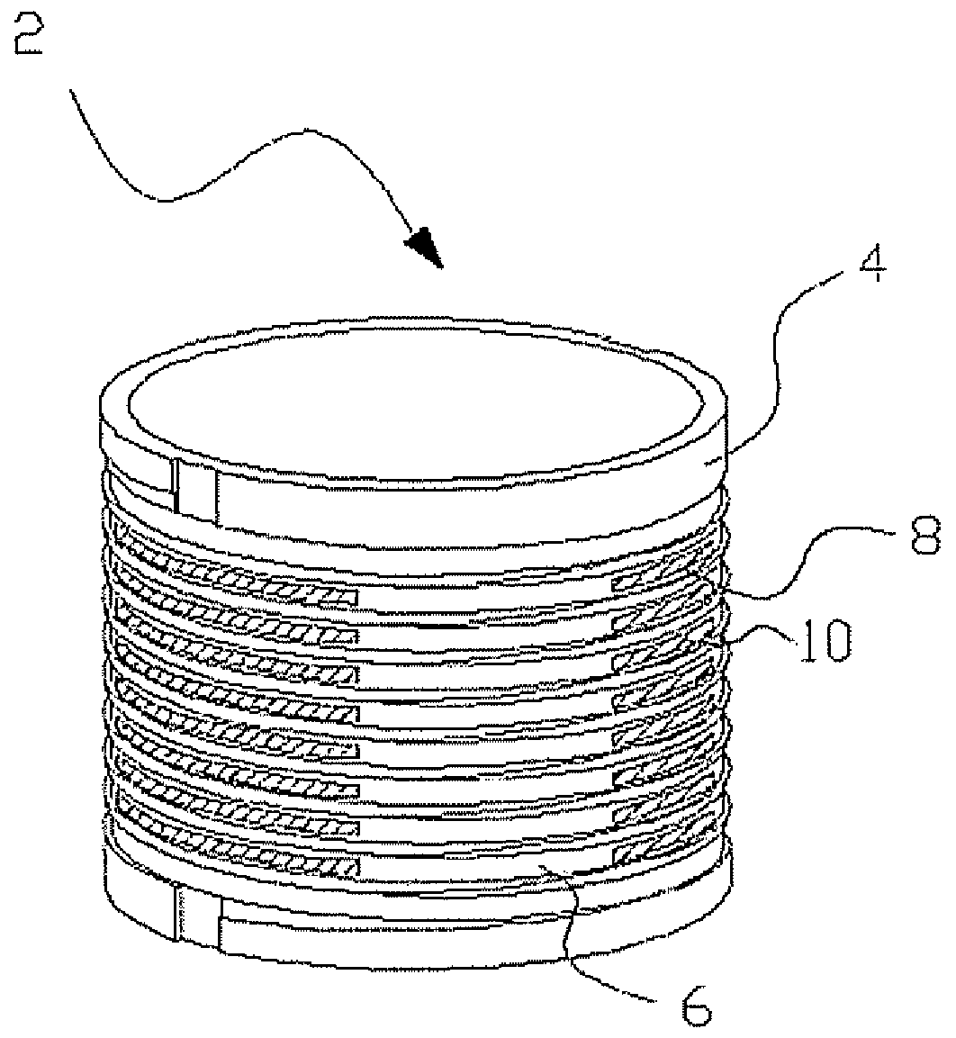
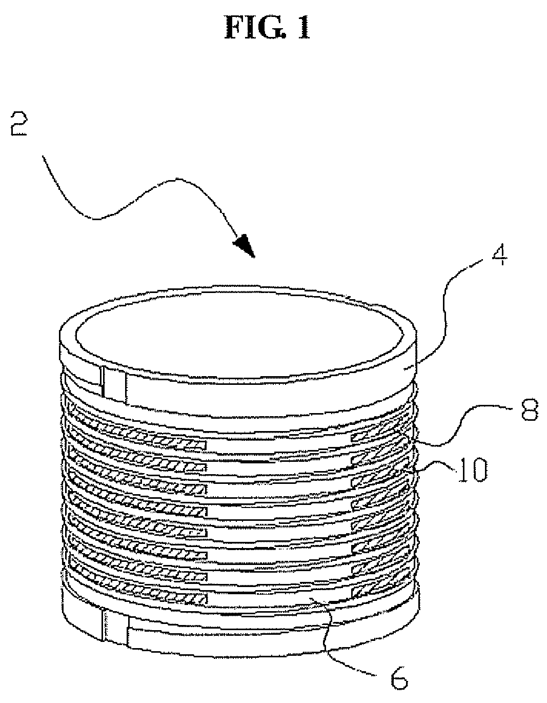
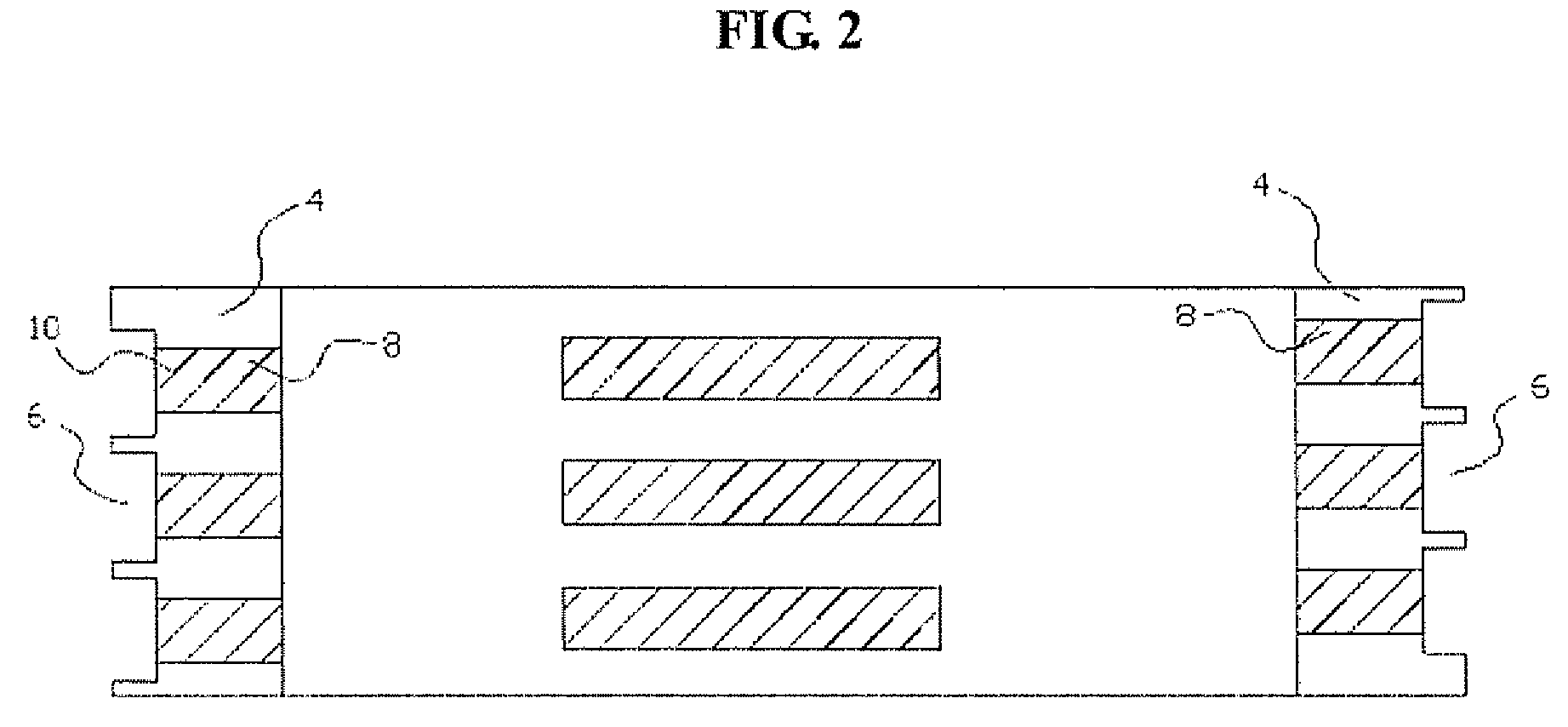
[0027]FIG. 1 is a perspective view showing a bobbin according to the present invention, FIG. 2 is a sectional view of the bobbin according to the present invention, and FIG. 3 is a sectional view of part of the bobbin according to the present invention.

[0028]As shown in FIGS. 1 to 3, a non-inductive winding wire-type solenoid bobbin 2 according to the present invention includes a bobbin body 4, winding grooves 6, and connection channels 8.

[0029]In this case, the bobbin body 4 serves to provide a place for winding a superconductive wire or the like. The bobbin body 4 has the shape of a hollow cylinder. Any material may be used for the bobbin body 4, as long as the material is not affected by magnetic fields. Preferably, the bobbin body 4 is made of glass-fiber reinforced plastic or insu...


PUM


Abstract

Disclosed herein is a non-inductive winding wire-type solenoid bobbin. The bobbin includes a cylindrical bobbin body, winding grooves formed on an outer circumferential surface of the bobbin body at regular intervals, and a connection channel provided on one side of each of the winding grooves. According to the present invention, an inner wire is in direct contact with liquid nitrogen through the connection channel, thus increasing the cooling effect when an electrical power system experiences trouble, and a superconducting fault current limiter including the bobbin limits a current, therefore minimizing damage to the inner wire, and makes a fast recovery after the fault current is limited to allow the current to resume flowing in the system.

Description

CROSS-REFERENCE TO RELATED APPLICATION[0001]This application claims priority to and the benefit of Korean Patent Application No. 10-2006-0019184 filed with the Korean Intellectual Property Office on Feb. 28, 2006, the entire content of which is incorporated herein by reference.BACKGROUND OF THE INVENTION[0002]1. Field of the Invention[0003]The present invention relates to a non-inductive winding wire-type solenoid bobbin, which improves the cooling effect of a bobbin applied to a resistance-type high temperature superconducting fault current limiter so as to reduce the fault current caused by a short circuit or a ground fault in of a large electrical power system.[0004]2. Description of the Related Art[0005]As is well known to those skilled in the art, a fault current limiter is a kind of circuit breaker that has no impedance under normal conditions, but when an abnormal voltage or current flows in an electrical power system due to a fault, such as lightning or a short circuit, impe...

Claims


Application Information

Patent Timeline
IPC IPC(8): H01F6/00
CPCH01F5/02H01F6/04H01L39/16H01F2006/001H01F6/06H10N60/30H01B12/14H02H9/023
Inventor YANG, SEONG-EUNAHN, MIN-CHOELPARK, DONG-KEUNKO, TAE-KUK
Owner IND ACADEMIC CORP FOUND YONSEI UNIV
Why Eureka
Try Eureka